


How to Check LM358 IC: A Low-Voltage Follower Test

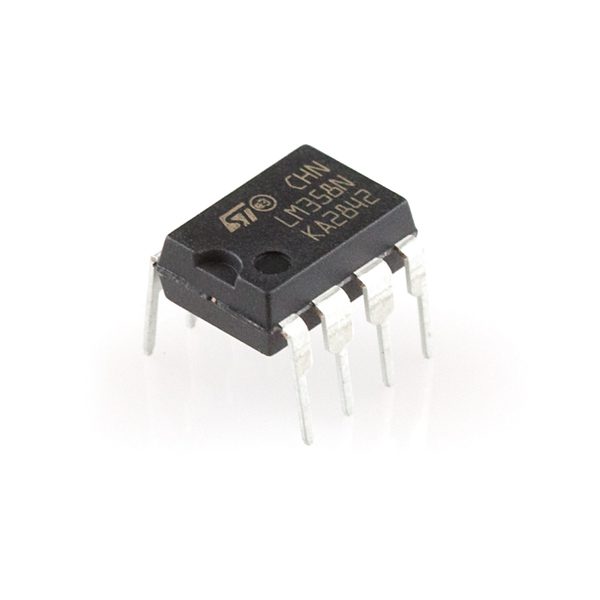
To check an LM358 IC, begin with a small low-voltage follower circuit operated comfortably inside its valid signal range. This can reveal a basic wiring or functional fault, but it does not verify every datasheet parameter or certify a part’s authenticity. Disconnect the device from unknown loads and identify its exact package first.
Inspect the package and supply connections

For a verified standard eight-pin part, connect the documented positive and low-supply pins to a supported current-limited source. A five-volt bench supply is a convenient example for a correctly identified compatible part, not a universal instruction for every analog IC. Check polarity before power and fit local bypassing close to the supply pins.
Build negative feedback for one amplifier
For amplifier one in the common pinout, connect output pin 1 to inverting input pin 2. Apply the test voltage to noninverting input pin 3. This is a unity-gain follower arrangement. Do not confuse the two inputs or leave the feedback wire open. Use a high-impedance meter at the output, not a speaker, motor or heavy load.
Choose a modest input well below the upper rail
Use a stable low-impedance test source in a conservative range, such as roughly 0.5–1.5 V with a suitable five-volt supply and light load. Confirm that range against the actual device. Avoid immediately sweeping the input to the positive supply, where ordinary LM358 common-mode and output limits can make a working part appear faulty.
Configure the unused amplifier safely
Do not leave unused inputs floating. Use a stable documented follower arrangement at a valid bias level, with no unintended output load. The unused half shares the supply and can affect behavior if left oscillating or driven outside its permitted range. Follow the manufacturer’s unused-amplifier guidance for the exact variant.
Compare input and output at several points
Measure the actual input at the pin and output relative to the same supply reference. A functional follower should track within its offset and operating limitations, not necessarily match every displayed digit. Record supply, load and meter resolution. A few steady readings do not measure bandwidth, noise, slew rate or full-temperature accuracy.
Diagnose saturation before declaring failure
An output stuck near one rail calls for checking pin orientation, supply, feedback continuity, input range and output loading. A wrong breadboard rail or input above the common-mode limit can mimic a bad IC. Check for oscillation with a suitable instrument if the circuit layout and load warrant it; a multimeter alone cannot rule out all dynamic faults.
Newest in the store


Keep the conclusion narrow
Passing this test supports basic operation of the tested channel under the recorded conditions. Repeat an equivalent controlled test for the second channel if needed. It is not proof of sourcing, guaranteed gain accuracy or safe behavior in a charger or protection circuit. Replace a part only after distinguishing a component fault from a circuit-design error.
Relevant Epro listing
Product information and prices were checked on 19 October 2026. This is a current snapshot, not a historical price associated with the publication timestamp. Stock, accessories and checkout prices can change. Listing claims are not independent performance or authenticity certifications.
| Product | Checked price | Stock |
|---|---|---|
| Op-Amp LM358 IC in Pakistan | PKR 24 | In stock |
Frequently asked questions
Must output equal input to the last meter digit?
No. Offset, meter limitations and operating conditions cause differences; compare against the relevant specifications.
Can this test prove the IC is genuine?
No. It is a limited functional test, not an authenticity or full-parameter verification.
Related Epro reading
Review breadboard connections before assembling a prototype. For controller expansion, the Mega 2560 pin guide explains why pin names and electrical limits must be checked together.
Technical references and test limitations
This guide uses the documentation linked below. The procedures are for a controlled, low-voltage learning setup; no independent hands-on test of the particular seller board is claimed. Record the actual part markings, wiring and firmware version before drawing conclusions from a test.