


Breadboard Connections: 7 Checks and a First LED Circuit

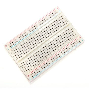
Breadboard connections are hidden underneath the plastic surface. Understanding those connections is more useful than copying a photograph hole by hole. Once you know which sockets share a conductor, you can trace a circuit, avoid short circuits and move parts without changing the design accidentally.
This guide covers a typical solderless breadboard and a low-voltage LED demonstration. Board layouts differ, so use a meter on the unpowered board to confirm the arrangement rather than treating every printed marking as authoritative.

1. Find the connected terminal strips
On a common breadboard, each short group of five holes forms one connected node. The next group along the board is separate. Placing both legs of a two-terminal component into the same connected group bypasses that component instead of placing it in the circuit.
The centre channel usually separates the two sets of terminal strips. It accommodates components such as suitable dual-inline integrated circuits, keeping the opposite rows of pins electrically separate. The channel is not itself a power rail.
2. Identify rails and possible breaks
Long side rails distribute supply and ground, but the left and right rails are not automatically joined. Some boards also split a long rail near the middle. A red line does not prove electrical continuity from one end to the other, and a blue line does not create a ground connection unless you wire one.
With all power sources disconnected, use continuity mode to map the rail segments and terminal strips. Check the meter itself first by touching its probes together. Never use continuity or resistance mode on a powered circuit.
3. Gather parts for a first LED circuit
Use a verified low-voltage regulated 3.3 V supply, a suitable ordinary indicator LED, a 330-ohm resistor, jumper wires and a 400-point breadboard or another board with known connections. Check the LED polarity from its datasheet or package markings; lead length and the flat edge are common clues but are not universal identifiers.
A resistor belongs in series with the LED. Do not connect the LED directly across a supply, even if it briefly lights. The current-limiting resistor is part of the electrical design, not an optional accessory.Newest in the store


4. Wire the LED path without power
- Connect the verified supply ground to the chosen ground rail.
- Connect the positive 3.3 V output to the chosen positive rail.
- Place a resistor from the positive rail to an unused terminal group.
- Put the LED anode in that resistor’s output group.
- Put the LED cathode in a different, unconnected terminal group.
- Connect the cathode group to ground with a jumper.
- Trace the complete path and check for a direct supply-to-ground short before applying power.
The resulting path is positive supply, resistor, LED and ground. The resistor may also be placed on the cathode side, provided it remains in the same series path. What matters is the electrical connection, not whether the resistor appears to the left or right in a photograph.
5. Estimate the current
For an illustrative LED forward voltage of 2.0 V, the approximate current is (3.3 − 2.0) / 330 = 0.0039 A, or 3.9 mA. Your actual LED forward voltage varies with type, current and temperature. Verify its permitted current and use a resistor with a suitable power rating; the calculation is not a universal specification for every LED.
If using a different supply voltage, recalculate instead of copying the resistor value blindly. A multi-LED arrangement also needs its own circuit analysis. Parallel LEDs should not be assumed to share current evenly through a single resistor.
6. Diagnose a dark or intermittent LED
Disconnect power before moving components. Check supply polarity, LED orientation, disconnected rail segments and whether both LED legs accidentally share one node. If the LED flickers when a wire moves, inspect the contact and jumper rather than immediately blaming the supply.
Measure the rail voltage in voltage mode after restoring power, taking care not to short adjacent contacts with the probe tips. A power module with the wrong jumper setting can supply the wrong voltage even when its indicator light appears normal.
7. Keep the board within its proper role
Use solderless boards for appropriate low-voltage prototyping, not mains circuits or high-current motor wiring. Keep layouts readable, label separate rails and add one subsystem at a time. For hardware choices see the breadboard price and accessory guide. SparkFun’s breadboard tutorial provides diagrams of the internal strips and explains why rail continuity needs checking.