


TPS22980 Power Mux: 7 Checks for Low-to-High Supply Handover

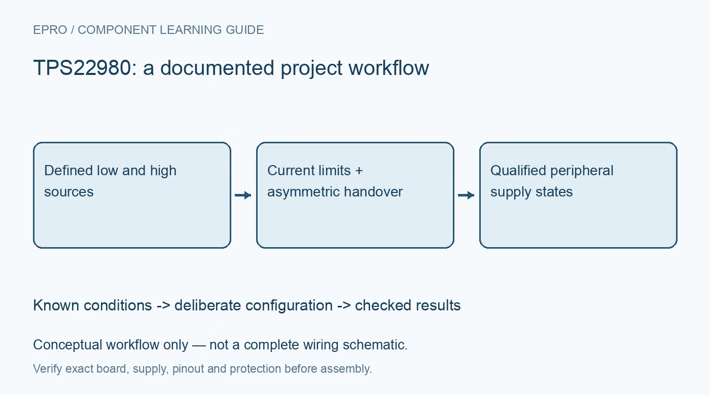
TPS22980 Power Mux: 7 Checks for Low-to-High Supply Handover
Plan TPS22980 current limits and asymmetric supply transitions before switching a peripheral between low- and high-voltage inputs. This is a documentation-based planning guide, not a report of independent hands-on testing.
1. Define both sources and the load voltage tolerance
The TPS22980 is a current-limited power mux that connects a peripheral to a low-voltage source or a higher-voltage source. It is not a regulator that converts either input to one fixed voltage. The low-voltage path operates from 3.0 V to 3.6 V, while the high-voltage switch has its own specified operating envelope. Confirm that the peripheral tolerates both intended voltages and the transition between them. Record source impedance and output capacitance before choosing control behavior. Manufacturer documentation.
2. Review the exact pin roles and bias supply
The device is powered from its 3.3-V path, so availability of a higher-voltage input does not remove the need to satisfy low-voltage supply requirements. Read the package pin table and reserved-pin instructions rather than using a generic dual-load-switch symbol. Review EN, HV_EN and S0 against the function table and logic thresholds. Define their reset states explicitly. A connector offering a high-voltage rail does not make that voltage acceptable on a digital control or current-setting terminal. Manufacturer documentation.
3. Set current limits for each supported state
External resistances establish the low-voltage switch current limit and the high-voltage limits associated with the documented operating states. Use the manufacturer equations, allowed resistance range and tolerance information instead of treating resistor values as exact current guarantees. Include load startup and capacitor charging in the budget. The low-voltage switch current range is specified separately from the high-voltage path, so do not infer one shared capability from the package name. Keep each resistor and intended operating state in the design record. Manufacturer documentation.
4. Understand the low-to-high transition mechanism
When high voltage and the corresponding enable condition are detected, the device can turn on the high-voltage switch while the low-voltage switch remains involved until reverse-current detection disables the latter path. This make-before-break behavior is an intentional part of the documented transition. It is not permission to parallel arbitrary supplies externally. Review supply sinking limits, wiring inductance and the expected load waveform. Qualify the output during the changeover rather than declaring a handover seamless merely because both steady-state voltages are correct. Manufacturer documentation.
Newest in the store


5. Treat high-to-low handover as a different event
The reverse transition first breaks the high-voltage connection and discharges the output toward the low-voltage level before reconnecting that path. The datasheet warns that with a load present, output can transition to zero before returning to 3.3 V. Therefore this is not a universal uninterrupted backup-power function. Determine whether the peripheral resets, loses state or violates its sequencing rules during that interval. A successful low-to-high test does not qualify the opposite direction, and output capacitance does not automatically eliminate the documented interruption. Manufacturer documentation.
6. Check energy and heat during limiting or discharge
Current limiting can leave substantial voltage across the active switch, creating dissipation even when load current appears bounded. Output-capacitor energy also needs a controlled discharge path during high-to-low handover. Assess duration, repetition rate, board copper and ambient temperature, not only a steady-state resistance calculation. Thermal shutdown is a protective response rather than an acceptable normal operating mode. Use a reviewed, current-limited setup for any fault testing and avoid connecting uncontrolled energy sources to an unqualified prototype. Manufacturer documentation.
7. Verify all meaningful transitions at the peripheral
Build a state-based test plan covering source arrival and removal, enable changes, both handover directions and the selected current-limit states. Measure at the peripheral as well as at the mux output to expose cable drop and local capacitance effects. Log control levels, source voltages, load demand and any reset indication. Describe the resulting interruption and recovery limits honestly. This documentation-based planning procedure does not claim that a particular module has been tested or that the mux guarantees continuity for every peripheral. Manufacturer documentation.
Related reading: TPS22976 Load Switch: 7 Checks for Two Bias-Controlled Rails.
Catalog note: The exact-part search did not return a matching Epro listing during preparation. Check the current catalog; this guide makes no price, availability or included-accessory claim.