


TPS22976 Load Switch: 7 Checks for Two Bias-Controlled Rails

TPS22976 Load Switch: 7 Checks for Two Bias-Controlled Rails
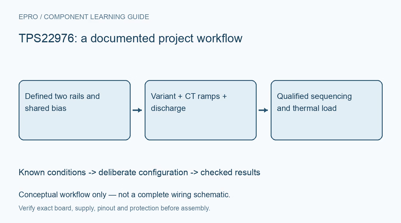
Plan TPS22976 dual rails with exact variant behavior, shared bias, independent timing capacitors, discharge paths and combined heat. This is a documentation-based planning guide, not a report of independent hands-on testing.
1. Select the exact base, A or N variant
The TPS22976 family contains base, A and N versions with different turn-on and discharge behavior. The base device includes quick output discharge, while the N variant omits it, and the A variant offers faster turn-on behavior. The device comparison table also distinguishes typical resistance entries, so do not apply a family headline to every version without checking. Confirm the complete ordering code and pin map before calculating startup. A nearly identical part marking can change an off-state function that the downstream load depends on. Manufacturer documentation.
2. Keep both inputs within the shared-bias relationship
The recommended input range begins at 0.6 V and extends to VBIAS, while the bias supply operates from 2.5 V to 5.7 V. Check the relationship for both channels during partial power, not just their normal nominal voltages. The quoted on-resistance depends on bias conditions and the exact variant. A low-voltage load rail does not eliminate the need for the higher bias supply. Record which source powers VBIAS and what happens when it collapses while one switched input remains present. Manufacturer documentation.
3. Give each ON control a defined reset state
ON1 and ON2 are active-high controls that must not float. Decide whether the loads start together or in a deliberate sequence and choose appropriate controller or hardware defaults. Review input logic levels separately from the switched voltage and bias rails. Include the case where only one channel should remain active after a fault or reset. Independent controls allow sequencing decisions but do not automatically enforce them, especially while a processor is booting or its control pins have not been configured. Manufacturer documentation.
4. Choose timing capacitors from actual load requirements
Each channel has its own timing capacitor, allowing a ramp to be selected for that rail. Use the documented relationship and operating conditions rather than assuming identical capacitor values produce an exact sequencing delay. Estimate charging current from output capacitance and slope, then include load current during startup. A very slow ramp may also conflict with peripheral reset or undervoltage behavior. Keep turn-on delay, output rise time and downstream readiness separate when choosing the final sequence and acceptable timing margin. Manufacturer documentation.
Newest in the store


5. Account for discharge and unintended back-power
The versions with quick discharge provide an internal path from disabled output to ground, with a documented typical resistance near 230 ohms. That path matters if another source or a signal connection maintains the load voltage. OFF is therefore not a generic isolated connection. Check the complete downstream circuit and the selected variant before using the switch for supply sharing. Qualify how long the output takes to fall and whether an intended short power-cycle interval actually removes power from the peripheral. Manufacturer documentation.
6. Add both channel losses before accepting current ratings
Six amperes per channel is conditional on electrical and thermal requirements; it is not an unconditional twelve-ampere capability for every board. Estimate conduction losses using the applicable resistance and temperature behavior, then add the shared package heating. Follow thermal-pad and copper guidance. Thermal shutdown is a protective response, not a preferred operating point or a programmable current limiter. Review upstream fault protection and define what repeated cooling-and-restart cycles would do to the loads if an excessive-current condition remains. Manufacturer documentation.
7. Verify independent and simultaneous startup cases
Begin with current-limited sources and representative load capacitance. Check each channel separately, then both together, observing the inputs, bias rail and outputs through startup, shutdown and rapid restart. Exercise the intended steady current long enough to assess temperature under actual board conditions. This guide claims no independently measured timing or thermal performance. Preserve the complete part suffix, timing capacitors and rail-source relationships with the accepted sequence so replacement parts or load changes receive a targeted review. Manufacturer documentation.
Related reading: TPS22966 Load Switch: 7 Checks for Two Controlled Rails.
Catalog note: The exact-part search did not return a matching Epro listing during preparation. Check the current catalog; this guide makes no price, availability or included-accessory claim.