


TPS92512 Buck LED Driver: 7 Checks for Controlled LED Current

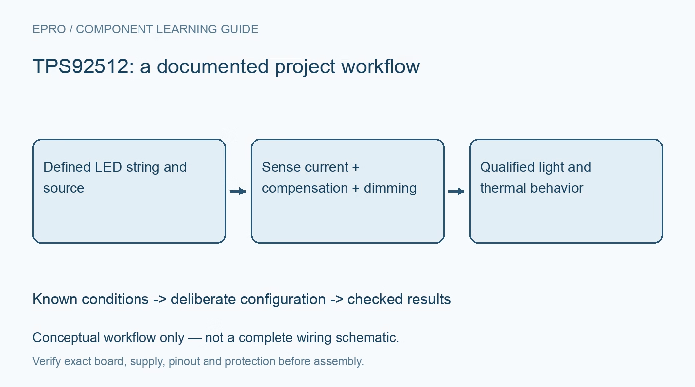
TPS92512 Buck LED Driver: 7 Checks for Controlled LED Current
Plan TPS92512 LED current, analog and PWM dimming, switching components and thermal limits without confusing the standard and HV variants. This is a documentation-based planning guide, not a report of independent hands-on testing.
1. Define a buck-compatible LED string
The TPS92512 is a step-down LED current regulator with an integrated high-side MOSFET and output capability up to 2.5 A under specified conditions. A buck stage needs adequate input voltage above the intended LED string voltage and circuit losses; it cannot boost an insufficient source. Document cold and hot LED forward voltage, maximum permitted current and source variation. Include wiring drop and startup conditions so the power-stage design addresses the actual string rather than a nominal LED voltage label. Manufacturer documentation.
2. Distinguish the standard device from the HV variant
The standard TPS92512 operates over a 4.5-V to 42-V input range, while the separately identified HV variant extends the input range to 60 V. A shared datasheet does not give the standard part the higher rating. Record the complete device identification and check all component voltage margins against the intended source and transients. These are nonisolated power circuits; neither variant is a direct mains interface. Use suitably protected sources and qualified handling practices for higher-voltage prototypes. Manufacturer documentation.
3. Set LED current from the sense relationship
The analog IADJ input controls the current reference, whose documented range extends to 300 mV using the specified input relationship. Use that reference and the sense-resistor equation to establish current, including tolerances and low-level dimming limitations. Calculate sense-resistor dissipation and temperature drift rather than choosing resistance alone. Keep its sensing connections faithful to the recommended layout. Current regulation is not the same as output-voltage regulation, and a measured LED voltage cannot substitute for verifying current through the intended string. Manufacturer documentation.
4. Design the complete switching power stage
The integrated high-side switch does not eliminate the external inductor, rectifier diode, capacitors or compensation network. Select switching frequency within the documented range and calculate ripple, peak inductor current, diode stress and effective capacitance for the worst operating point. Check inductor saturation and heating with margin beyond nominal LED current. Follow the compensation procedure rather than copying values from an unrelated string voltage. A visibly steady LED can conceal excessive ripple, a saturated inductor or an unstable current-control loop. Manufacturer documentation.
Newest in the store


5. Separate analog adjustment from PWM dimming
IADJ and PDIM serve different dimming functions. Analog control changes the current setpoint, while PWM dimming gates the current according to the documented timing behavior. Assign each control a clear owner and ensure its voltage levels and default states are valid. Review minimum useful pulse behavior, transient response and audible or visible artifacts for the application. A ten-percent command is not automatically ten-percent optical output, particularly when pulses approach settling intervals or the LED current becomes too small for accurate regulation. Manufacturer documentation.
6. Qualify startup and fault-energy behavior
Use the adjustable undervoltage-lockout guidance to define when the converter may start and stop. Review open-string and transient behavior, including the manufacturer discussion of output ringing and clamp components where applicable. Ensure protection parts have suitable voltage, current and energy ratings. Cycle-by-cycle overcurrent protection and thermal shutdown are safeguards, not substitutes for a properly rated inductor or a normal thermal design. Any intentional fault test needs a reviewed fixture; do not disconnect a high-current energized string casually to observe what happens. Manufacturer documentation.
7. Verify electrical current before judging optical performance
Begin with a suitable bounded setup and conservative current, then verify startup, regulated current, ripple and both dimming paths. Measure stabilized temperatures of the IC, inductor, diode and sense resistor under the intended enclosure conditions. Compare light output only after the electrical path passes, using a repeatable optical arrangement rather than visual impressions alone. Save input voltage, string details, settings and observed limits. This guide describes a manufacturer-based qualification plan, not independent proof that a particular module achieves every headline current or dimming ratio. Manufacturer documentation.
Related reading: TLC5947 LED Driver: 7 Checks for Safe Startup and PWM Frames.
Catalog note: The exact-part search did not return a matching Epro listing during preparation. Check the current catalog; this guide makes no price, availability or included-accessory claim.