Getting Started with NodeMCU ESP8266 Projects
Getting Started with NodeMCU ESP8266 Projects
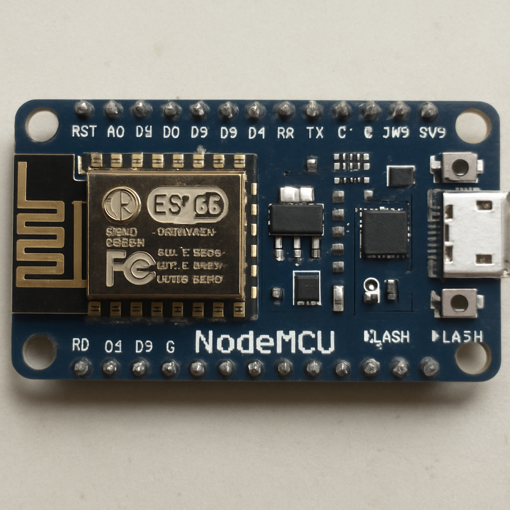
The NodeMCU ESP8266 is a powerful microcontroller that has captured the attention of hobbyists and professionals alike. Its integration of Wi-Fi capabilities and ease of use make it ideal for Internet of Things (IoT) projects. If you’re looking to dive into the world of ESP8266 projects, you’re in the right place. In this guide, we will cover everything from understanding the NodeMCU firmware and ESP8266 pinout, to programming and setting up your first project.

NodeMCU is an open-source firmware and development kit that helps you prototype or build IoT products. It’s based on the ESP8266 Wi-Fi module, which is a low-cost Wi-Fi microchip with a full TCP/IP stack and microcontroller capability. The NodeMCU firmware runs on the ESP8266 Wi-Fi SoC from Espressif Systems and is built on the eLua project. It uses many open-source projects, such as lua-cjson, and spiffs.
Why Choose NodeMCU ESP8266 for Your Projects?
Here are some compelling reasons to consider the NodeMCU ESP8266 for your IoT projects:
- Cost-Effective: It offers a low-cost solution for adding Wi-Fi capabilities to your projects.
- Community Support: With a large community, you’ll find countless resources, tutorials, and examples.
- Ease of Use: The integration with Lua scripting makes it easy for beginners.
- Versatile: Suitable for a wide range of applications, from simple data logging to complex automation systems.
Understanding the ESP8266 Pinout

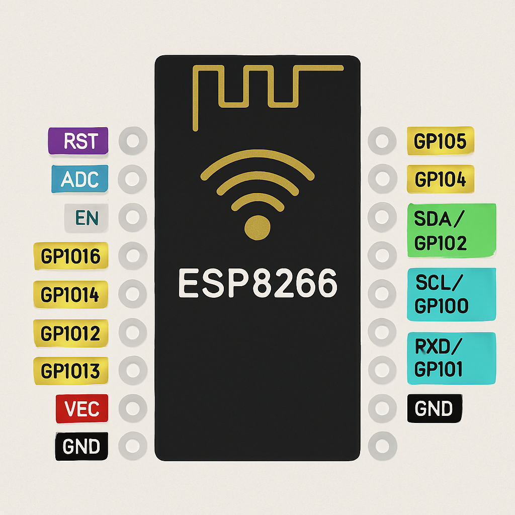
The ESP8266 GPIO (General Purpose Input Output) pins are versatile and can be used for various functions. Understanding the pinout is crucial for setting up your projects correctly.
Key Pins and Their Functions
- GPIO Pins: These are used for digital input and output. They can be configured as INPUT, OUTPUT, or INPUT_PULLUP.
- ADC (Analog to Digital Converter): The NodeMCU has one ADC pin (A0), which can be used to read analog signals.
- UART (Universal Asynchronous Receiver-Transmitter): For serial communication.
- SPI (Serial Peripheral Interface) and I2C (Inter-Integrated Circuit): Used for communication with other devices.
Setting Up Your NodeMCU ESP8266
Setting up your NodeMCU ESP8266 for the first time involves a few steps, from installing the necessary drivers to uploading your first program. Let’s get started.
Step 1: Install USB Drivers
To communicate with your NodeMCU board, you need the appropriate USB drivers. Most ESP8266 boards use the CP2102 or CH340 USB-to-serial chip. Visit the manufacturer’s website to download and install the drivers.
Step 2: Install the Arduino IDE
The Arduino IDE is a popular choice for programming the ESP8266. It’s user-friendly and has extensive libraries that support the NodeMCU. Download and install the Arduino IDE from the official website.
Step 3: Add ESP8266 Board Manager
In the Arduino IDE, navigate to File > Preferences. In the “Additional Boards Manager URLs” field, add the following URL: http://arduino.esp8266.com/stable/package_esp8266com_index.json. Then, go to Tools > Board > Boards Manager, search for “ESP8266”, and install the package.
Step 4: Select Your Board and Port
Connect your NodeMCU to your computer. In the Arduino IDE, go to Tools > Board and select “NodeMCU 1.0 (ESP-12E Module)”. Then, under Tools > Port, select the port that your NodeMCU is connected to.
Your First NodeMCU ESP8266 Project

by Compare Fibre (https://unsplash.com/@comparefibre)
Newest in the store
Let’s create a simple project: controlling an LED via Wi-Fi using the NodeMCU ESP8266.
Components Required
- NodeMCU ESP8266 board
- LED
- Resistor (220 Ohms)
- Breadboard and jumper wires
Circuit Setup
- Connect the anode (long leg) of the LED to GPIO pin D1 on the NodeMCU.
- Connect the cathode (short leg) of the LED to a 220 Ohm resistor.
- Connect the other end of the resistor to the GND (Ground) pin on the NodeMCU.
Programming the NodeMCU
Open the Arduino IDE and enter the following code:
#include
const char* ssid = “your_SSID”; const char* password = “your_PASSWORD”;
void setup() { Serial.begin(115200); WiFi.begin(ssid, password);
while (WiFi.status() != WL_CONNECTED) { delay(500); Serial.print(“.”); }
Serial.println(“WiFi connected”); pinMode(D1, OUTPUT); }
void loop() { digitalWrite(D1, HIGH); delay(1000); digitalWrite(D1, LOW); delay(1000); }
Upload and Test
Upload the code to your NodeMCU. Once uploaded, the LED should blink on and off every second, indicating that your NodeMCU is successfully connected to your Wi-Fi network and executing the code.
Exploring NodeMCU Applications
The NodeMCU ESP8266 opens up a world of possibilities for IoT applications. Here are a few examples:
- Home Automation: Control lights, fans, and appliances remotely.
- Weather Stations: Collect and analyze environmental data.
- Security Systems: Monitor and alert for unauthorized access.
- Smart Gardening: Automate watering systems based on soil moisture levels.
Conclusion
The NodeMCU ESP8266 is a versatile and powerful platform that offers an accessible entry point into IoT projects. By understanding its pinout, setting up the necessary software, and experimenting with simple projects, you can harness the full potential of this microcontroller. Whether you’re a beginner or an experienced developer, the NodeMCU ESP8266 provides endless opportunities to innovate and create.
Happy tinkering!


