Understanding the ESP8266 Pinout Diagram
Understanding the ESP8266 Pinout Diagram
The ESP8266 has become a popular microcontroller for a variety of projects due to its low cost and built-in WiFi capabilities. Whether you’re a hobbyist or a professional, understanding the ESP8266 pinout diagram is crucial for designing and building your projects. This guide will help you navigate the ESP8266 pin layout, providing insights into how to effectively use its GPIO pins for your electronics projects.
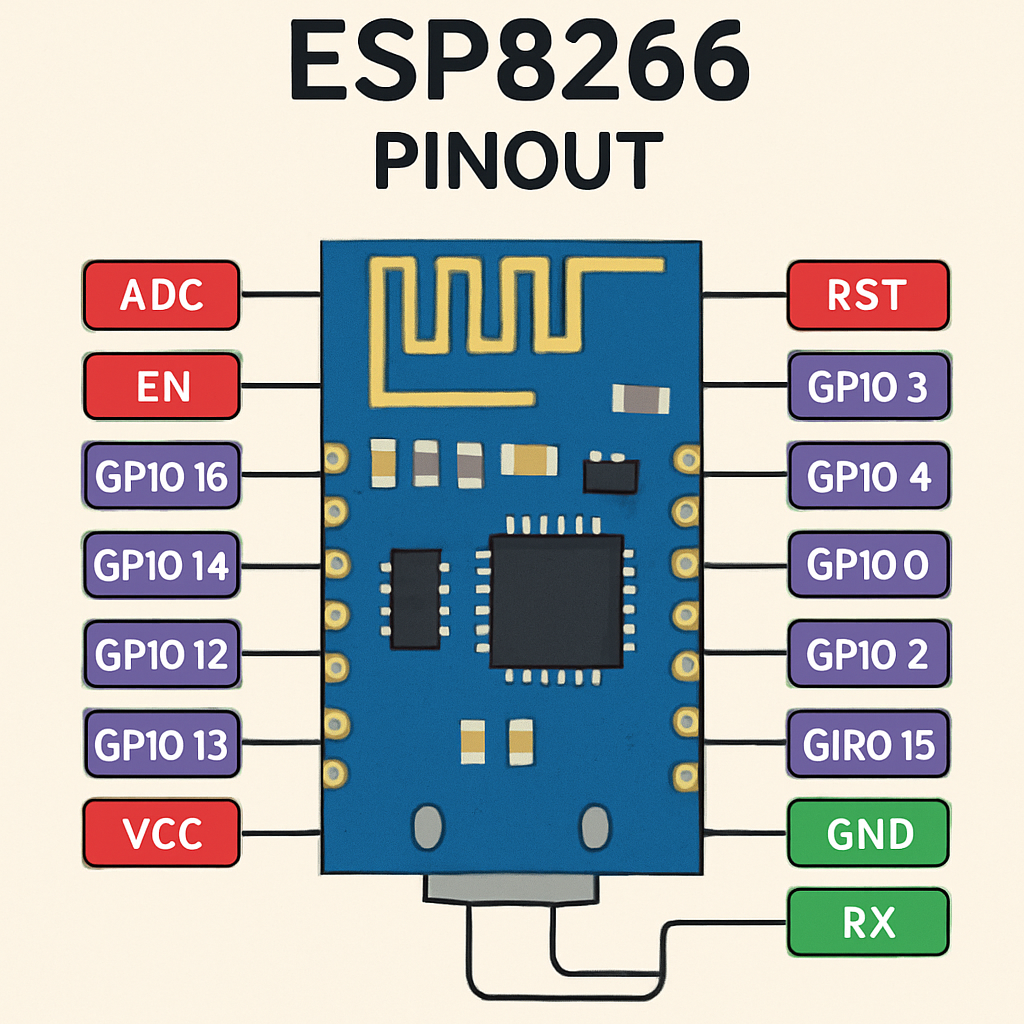
The ESP8266 module comes in several variations, but the most common ones are the ESP-01, NodeMCU, and the D1 Mini. Each of these modules has a different pinout configuration, yet they share the same core ESP8266 chip. Understanding the pinout of these variations is essential for utilizing their full potential in your projects.
ESP8266EX Pinout
The ESP8266EX is the chip that powers the various ESP8266 modules. Its pinout includes several General Purpose Input/Output (GPIO) pins, which can be configured for different functions. The chip has a total of 17 GPIO pins, each capable of performing multiple roles, from digital input/output to PWM, I2C, SPI, and even UART communication.
NodeMCU ESP8266 Pinout
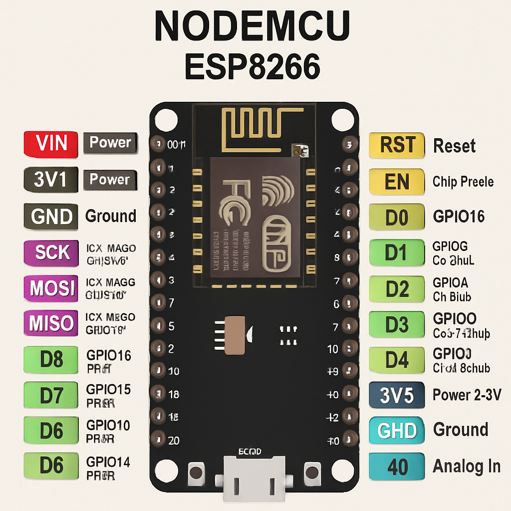
NodeMCU is a popular choice among developers due to its compatibility with the Arduino IDE and its ease of use. The NodeMCU board exposes all the GPIO pins of the ESP8266, making it easier to connect sensors, actuators, and other modules. The NodeMCU pinout diagram is straightforward, with labeled pins for power, ground, and GPIO functions.
D1 Mini Pinout
The D1 Mini is a compact board that offers a smaller footprint than the NodeMCU while still providing access to most of the ESP8266’s features. Its pinout includes power pins, ground pins, and several GPIO pins that are compatible with a wide range of modules and sensors. The D1 Mini is ideal for projects where space is limited.
ESP8266 GPIO Pin Mapping
The GPIO pins on the ESP8266 are versatile and can be used for a variety of functions. Understanding the pin mapping is crucial for setting up your projects correctly. Each GPIO pin can be configured as an input or output, and many pins support additional functions such as PWM, ADC, or UART.
Using GPIO Pins
When working with the ESP8266, it’s important to note the limitations of some GPIO pins. For example, certain pins are used during the boot process and should not be pulled high or low at startup. Consulting the ESP8266 schematic and documentation can help you understand these limitations and plan your design accordingly.
Understanding the ESP8266 Schematic
Newest in the store
by Growtika (https://unsplash.com/@growtika)
The ESP8266 schematic provides a detailed view of the chip’s internal connections and functionalities. It includes information about the power requirements, oscillator settings, and the internal memory structure. Familiarizing yourself with the schematic is beneficial for troubleshooting and optimizing your projects.
Power and Ground Connections
The ESP8266 requires a 3.3V power supply for operation. Most development boards, like the NodeMCU and D1 Mini, include voltage regulators to step down from 5V USB power. Ensuring proper power and ground connections is crucial for stable operation and to prevent damage to the chip.
ESP8266 Pin Configuration
Configuring the ESP8266 pins for your specific needs involves setting them up as inputs or outputs and assigning their roles. This configuration is typically done in the setup section of your Arduino sketch or using AT commands if you are programming the ESP8266 directly.
Digital Input and Output
The GPIO pins can be configured for digital input and output using functions such as pinMode(), digitalWrite(), and digitalRead(). These functions allow you to control LEDs, read button states, and interface with digital sensors.
Analog Input
The ESP8266 features a single analog input pin (ADC0), which is used to read analog signals from sensors. This pin can be used to measure voltages from 0 to 1V, so a voltage divider may be necessary to read higher voltages.
ESP8266 Wiring and Connections
Proper wiring is essential for successful project implementation. Poor connections can lead to unreliable performance or even damage the ESP8266. Using breadboards, jumper wires, and soldered connections can help ensure stable and reliable wiring.
Common Wiring Mistakes
A common mistake when working with the ESP8266 is incorrectly wiring the power supply. Always double-check your connections before powering on the device to avoid issues. Additionally, ensure that your GPIO pins are correctly configured in your code to avoid conflicts or unexpected behavior.
Conclusion
Understanding the ESP8266 pinout diagram is fundamental for anyone looking to harness the power of this versatile microcontroller. By familiarizing yourself with the pin configurations, GPIO mapping, and wiring practices, you can confidently embark on any project, from simple IoT devices to complex automation systems. As you continue to explore the capabilities of the ESP8266, you’ll find that its flexibility and power open up a world of possibilities for your electronic designs.


