


Understanding the Basics of digital circuits

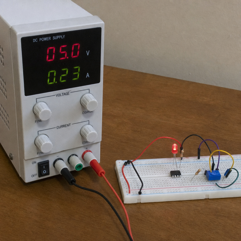
Understanding the Basics of digital circuits
The Basics of digital circuits start with a simple idea: electronic systems can represent information using defined signal levels, usually described as 0s and 1s. From calculators and timers to microcontrollers, sensors, and everyday consumer devices, digital circuits make it possible for hardware to store, process, and respond to information in predictable ways. This guide explains the core concepts, the role of common electronic components, and how beginners can connect theory to practical electronics projects.
What are digital circuits?
Digital circuits are electronic circuits that operate using discrete signal states rather than continuously varying values. In most beginner explanations, those states are called LOW and HIGH, or 0 and 1. The circuit does not need to interpret every possible voltage in between; instead, it responds based on whether a signal falls within a defined range.
That distinction is what makes digital electronics so useful. A digital device can count pulses, compare logic states, store bits of data, and make decisions based on input conditions. When you press a button on a simple electronic game, enter a number on a keypad, or use a programmable controller, digital logic is working behind the scenes.
At a practical level, learning digital circuits means learning how signals move through components such as switches, resistors, LEDs, transistors, logic gates, integrated circuits, and power connections. Once you understand how these pieces interact, even complex systems become easier to break down into smaller, understandable blocks.

The core idea behind digital signals
A digital signal is designed to be interpreted as one of a limited number of states. In binary digital electronics, that usually means two states. A LOW signal might represent false, off, or 0, while a HIGH signal might represent true, on, or 1.
The exact voltage depends on the circuit family and design. For example, one system may use 5 volts as a HIGH level, while another may use 3.3 volts. What matters is that the components in the circuit agree on which voltage ranges count as LOW and which count as HIGH.
This makes digital systems more resistant to small amounts of noise than many purely continuous systems. If a signal is slightly imperfect but still falls within the recognized HIGH range, the circuit can treat it as HIGH. That reliability is one reason digital electronics became the foundation for computers, embedded systems, and modern control devices.
How do digital circuits differ from analog circuits?
Digital circuits work with defined logic states, while analog circuits work with continuously changing signals. An analog circuit may amplify a microphone signal, filter audio, regulate voltage, or measure a sensor output that changes smoothly over time. A digital circuit, by contrast, usually decides whether a signal is on or off, counts events, or processes binary data.
Neither type is “better” in every situation. They solve different problems. Many real-world devices use both: an analog section may receive or condition a real-world signal, and a digital section may process that signal, store data, or control an output.
For example, a temperature sensor might produce an analog voltage. That signal may be filtered or amplified, then converted into digital data so a microcontroller can display a reading or activate a fan. Understanding both digital and analog behavior gives you a stronger foundation for complete circuit design.
Key differences include:
- Signal type: Analog signals vary continuously; digital signals use defined states.
- Typical purpose: Analog circuits often handle sensing, audio, power regulation, and amplification; digital circuits handle logic, counting, memory, and control.
- Noise behavior: Digital circuits can often ignore small signal variations if voltage thresholds are still met.
- Design approach: Analog design often focuses heavily on gain, frequency response, impedance, and stability; digital design focuses on logic levels, timing, sequencing, and data flow.
Essential electronic components in digital circuits
Digital circuits are built from basic components that guide current, set voltage levels, switch signals, and display outputs. You do not need to memorize every part before you begin, but you should understand what each common component contributes.
Resistors limit current and create voltage drops. In digital projects, they are often used with LEDs, pull-up inputs, and pull-down inputs. A pull-up or pull-down resistor helps prevent an input from floating in an unpredictable state.
Switches and push buttons provide simple human input. When pressed, they can connect a circuit node to power or ground. In practical circuits, they may also need debouncing because mechanical contacts can create rapid on-off transitions when pressed.
LEDs provide a visible output. They are excellent learning tools because they show whether a signal is HIGH, LOW, blinking, or responding to logic.
Diodes allow current to flow mainly in one direction. They are often used for protection, signal steering, or preventing reverse current in simple designs.
Transistors act as electronic switches or amplifiers. In digital circuits, a transistor can let a low-current control signal operate a higher-current load such as a relay, motor, or brighter LED strip.
Integrated circuits, often called ICs or chips, contain many internal components in a compact package. Logic gates, timers, counters, shift registers, memory devices, and microcontrollers are all examples of ICs that make digital systems practical.
Capacitors store and release electrical charge. In digital circuits, they are frequently used for power supply smoothing, timing, filtering, and switch debouncing.
Logic gates are the building blocks
Logic gates are among the most important concepts in digital electronics. They take one or more input signals and produce an output based on a defined rule. Once you understand gates, you can see how more advanced digital systems perform decisions.
The common logic gates include:
- NOT gate: Inverts the input. HIGH becomes LOW, and LOW becomes HIGH.
- AND gate: Outputs HIGH only when all required inputs are HIGH.
- OR gate: Outputs HIGH when at least one input is HIGH.
- NAND gate: Outputs the opposite of an AND gate.
- NOR gate: Outputs the opposite of an OR gate.
- XOR gate: Outputs HIGH when inputs differ.
- XNOR gate: Outputs HIGH when inputs match.
A useful way to learn gates is to connect switches as inputs and LEDs as outputs. This turns abstract logic into something visible. When you change the switches, you can immediately see how the output responds.
Logic gates can also be combined. A simple alarm circuit might turn on a buzzer only when a door sensor is active and the system is armed. A digital lock may compare an entered code with a stored pattern. Larger systems use the same logic principles, just arranged in more sophisticated ways.
Circuit theory gives the basics structure
Circuit theory explains how voltage, current, resistance, power, and signal behavior interact. Even when working with digital logic, you still need these fundamentals because every digital signal exists in a physical electrical circuit.
Ohm’s law is one of the first tools beginners should learn. It helps you choose resistor values, estimate current, and avoid damaging LEDs or chips. Power calculations also matter because components can overheat or fail if they are asked to handle more energy than they are designed for.
Kirchhoff’s laws are also useful. They help explain how current flows through branches and how voltages add around loops. While a beginner may not use formal equations for every small project, the mental model is valuable: current must have a complete path, voltage must be referenced to something, and every connection affects the rest of the circuit.
In digital design, theory also extends to timing. Signals do not move through real components instantly. Gates have propagation delay, capacitors take time to charge, and clocks coordinate when data changes. These details become increasingly important as circuits become faster or more complex.
The power supply is the foundation
A reliable electronic circuits power supply is essential because digital circuits depend on stable voltage levels. If the supply is noisy, underpowered, reversed, or unstable, the logic may behave unpredictably even if the wiring looks correct.
For small breadboard projects, beginners often use batteries, USB power modules, or regulated bench supplies. The key is to match the voltage and current needs of the components. A 5-volt logic IC should not be casually connected to a higher voltage supply unless the datasheet allows it.
Good power habits include:
- Confirm the required voltage before connecting power.
- Check polarity so positive and ground are not reversed.
- Use current-limiting resistors for LEDs and similar loads.
- Add decoupling capacitors near IC power pins when appropriate.
- Keep ground connections common when different modules need to communicate.
- Turn off power before rewiring to reduce accidental shorts.
Many beginner problems are not caused by faulty parts or complicated logic. They come from missing ground connections, loose wires, weak batteries, overloaded supplies, or incorrect voltage assumptions. Treat power as part of the design, not an afterthought.

From simple switches to memory and timing
Digital circuits become more powerful when they can remember states or respond in a timed sequence. A basic switch gives an immediate input, but memory components allow a circuit to store information after the input changes.
A latch can hold a state until another signal changes it. A flip-flop stores one bit of information and is often controlled by a clock signal. Registers combine multiple flip-flops to store several bits. Counters advance through a sequence of states, often one step per clock pulse.
Timing circuits are also important. A timer IC, oscillator, or microcontroller clock can create pulses that coordinate events. For example, a blinking LED circuit uses timing to turn an output on and off repeatedly. A digital counter may use each pulse to advance a display or sequence through outputs.
These concepts lead naturally into more advanced digital systems. Once you understand how a circuit stores one bit, you can better understand memory, data registers, communication buses, and basic computer architecture.
Circuit analysis makes behavior predictable
Circuit analysis is the process of figuring out what a circuit should do before or while you build it. In digital electronics, that may include checking logic states, current paths, voltage levels, timing, and component limits.
For simple circuits, analysis may be as basic as asking: When this switch is pressed, where does current flow? Is the input pulled HIGH or LOW when the switch is open? Does the LED have a resistor? Are all grounds connected?
Newest in the store


For more advanced circuits, analysis may include truth tables, timing diagrams, Boolean expressions, or datasheet review. A truth table lists every relevant input combination and the expected output. A timing diagram shows how signals change over time. Boolean expressions describe logic relationships in a compact form.
A practical beginner checklist for circuit analysis includes:
- Identify the power and ground rails.
- Mark each input, output, and control signal.
- Determine the normal state of each input.
- Trace what happens when each switch or sensor changes.
- Check whether any component could receive too much current.
- Compare your expected output with what the circuit actually does.
- Review datasheet pinouts before wiring ICs.
Analysis does not remove all trial and error, but it makes experimentation safer and more productive. Instead of randomly moving wires, you test a clear expectation.
Circuit simulation helps you learn before you build
Circuit simulation lets you test ideas on a computer before assembling hardware. A simulator can show voltage levels, current paths, logic states, timing waveforms, and component behavior. This is especially helpful when you are learning because it allows quick mistakes without burned parts or messy rewiring.
Simulation is not a perfect replacement for building real circuits. Physical parts have tolerances, wires can be loose, breadboards can have contact issues, and real power supplies can sag under load. Still, simulation is excellent for understanding cause and effect.
Use simulation when you want to:
- Test a logic gate combination before wiring it.
- Check LED resistor values.
- Visualize capacitor charging and timing.
- Explore counters, flip-flops, and clocks.
- Compare digital and analog circuit behavior.
- Practice circuit troubleshooting with controlled faults.
A good habit is to sketch the circuit, simulate it, build it, and then compare the results. If the real circuit behaves differently, the difference becomes a learning opportunity. You may discover a wiring mistake, a missing ground, a switch bounce issue, or a limitation in the simulation model.
Circuit troubleshooting is a skill, not a guess
Troubleshooting digital circuits becomes easier when you follow a repeatable process. The goal is not to poke randomly at the circuit until something changes. The goal is to isolate the problem step by step.
Start with power. Measure the supply voltage at the circuit, not just at the source. A battery may read correctly when disconnected but drop under load. A breadboard rail may not be connected all the way across. A module may require a common ground that is missing.
Next, check orientation and pinouts. LEDs, diodes, transistors, ICs, and polarized capacitors must be placed correctly. Many IC problems come from reading the package backward or assuming all chips share the same pin arrangement.
Then test one section at a time. If an LED output does not work, check whether the LED works independently. If a logic gate output is wrong, verify each input state. If a clock is not advancing a counter, confirm the clock signal before blaming the counter.
A practical troubleshooting sequence looks like this:
- Inspect visually: Look for loose wires, wrong rows, reversed parts, and accidental shorts.
- Verify power: Measure voltage between the correct power and ground pins.
- Confirm references: Make sure all communicating sections share ground.
- Test inputs: Check whether switches, sensors, or logic signals are reaching the circuit.
- Test outputs: See whether the output device works when driven correctly.
- Divide the circuit: Separate the design into blocks and test each block.
- Change one thing at a time: Avoid creating new problems while fixing the old one.
This method is slower than guessing at first, but it becomes much faster as projects grow. It also builds confidence because each measurement tells you something useful.
Electronic amplifier circuits still matter in digital projects
Although digital circuits focus on logic states, electronic amplifier circuits often appear around them. Sensors, microphones, antennas, and other real-world inputs may produce signals too small or weak for a digital input to read reliably. An amplifier can increase signal strength or prepare the signal for further processing.
Amplifiers can also drive outputs. A microcontroller or logic IC pin may not be able to power a motor, speaker, relay, or high-brightness LED directly. A transistor driver, MOSFET stage, or amplifier circuit can let a small digital signal control a larger load safely.
This is where the boundary between analog and digital becomes practical rather than theoretical. A digital controller might make decisions, but analog support circuits often help it sense the world and act on it. Learning both areas gives you more flexibility and fewer design surprises.
Beginner-friendly kits and learning paths
Many people first encounter electronics through kits. Products such as electronic snap circuits 300 and elenco electronic snap circuits jr are popular because they reduce the friction of loose wiring and component handling. Snap-together parts make it easier to focus on cause and effect before moving into breadboards and soldering.
Some learners also search for legos electronic circuits when they want a building-block style approach that feels familiar and hands-on. The broader idea is useful: modular learning helps beginners experiment without needing to design every connection from scratch. Once the basic concepts are clear, moving to standard components becomes less intimidating.
A sensible learning path might look like this:
- Start with snap-together or guided kits to learn basic behavior.
- Build simple LED, switch, and buzzer circuits.
- Move to breadboards for flexible wiring.
- Learn logic gates, timers, counters, and transistors.
- Use simulation to test ideas before building.
- Try small microcontroller projects.
- Begin simple soldering and permanent builds.
- Explore basic pcb design when circuits become too complex for a breadboard.
Books and reference collections can also help, but choose them carefully. Searches like encyclopedia of electronic circuits or encyclopedia of electronic circuits volume 8 pdf may lead to useful historical references, but make sure you use legal and reliable sources. Older circuit collections can inspire ideas, yet component availability, safety expectations, and design practices may have changed.
PCB design turns a working circuit into a durable build
Breadboards are excellent for experiments, but they are not ideal for permanent projects. Wires can loosen, connections can be noisy, and larger designs become difficult to manage. That is why many hobbyists and engineers eventually move from breadboards to printed circuit boards.
PCB design organizes the circuit into copper traces, pads, component footprints, connectors, and mounting features. A well-designed PCB can make a project smaller, stronger, easier to repeat, and more professional. It also forces you to think carefully about layout, power routing, signal paths, and component placement.
For beginners, the first PCB should be simple. A small LED controller, logic gate board, sensor interface, or power distribution board is better than a large, crowded design. The goal is to learn the process without making every possible mistake at once.
Good beginner PCB habits include:
- Start from a tested schematic.
- Use correct component footprints.
- Label connectors clearly.
- Keep power traces appropriate for expected current.
- Place decoupling capacitors close to IC power pins.
- Avoid routing signals in confusing loops.
- Leave test points for important signals.
- Review the board carefully before ordering or fabricating it.
PCB layout is part engineering and part communication. A clear board helps the builder, the troubleshooter, and anyone who may revisit the project later.
Practical electronics projects for learning digital circuits
The best way to understand digital circuits is to build small projects that teach one concept at a time. A project does not need to be impressive to be valuable. In fact, the most useful beginner projects are often simple enough that you can fully understand them.
Try these project ideas:
- LED logic tester: Use LEDs to display HIGH and LOW states from switches or logic outputs.
- Two-switch AND circuit: Turn on an LED only when two switches are active.
- Simple alarm: Combine a switch, buzzer, and transistor driver.
- Debounced button circuit: Compare a raw button signal with a cleaned-up version.
- Timer-based blinker: Use a timing circuit to flash an LED.
- Digital counter: Use clock pulses to advance a count and show outputs.
- Shift register LED display: Control multiple LEDs with fewer control lines.
- Sensor threshold project: Use an analog sensor stage with a digital decision output.
- Mini traffic light: Sequence LEDs using timing and logic.
- Microcontroller input-output project: Read a button and control several outputs.
For each project, write down what you expect before powering it. Then record what actually happens. This simple habit turns every build into a small experiment and improves both your intuition and your troubleshooting ability.
Common beginner mistakes to avoid
Most early electronics mistakes are normal and fixable. The important thing is to recognize patterns so you can prevent them next time.
One common mistake is leaving inputs floating. A floating digital input is not clearly HIGH or LOW, so it may respond randomly to noise or nearby signals. Pull-up and pull-down resistors solve this by giving the input a known default state.
Another mistake is forgetting current limits. LEDs need resistors or another form of current control. IC pins have limits. Motors and relays often require driver circuits and protection components. Digital does not mean “no current concerns.”
Beginners also sometimes connect modules together without a shared ground. If two parts of a circuit do not share a reference, one device may not correctly understand the signal from another. This is a simple issue, but it can cause confusing symptoms.
Finally, many learners skip documentation. Even a quick sketch, note, or labeled photo can save time later. When you return to a project after a few days, clear notes help you remember what each wire and component was supposed to do.
A simple mindset for long-term progress
Learning digital circuits is easier when you stop expecting every project to work the first time. Electronics is a hands-on subject, and mistakes are part of the process. A circuit that fails in an understandable way can teach more than a circuit that works by accident.
Build slowly. Test often. Use datasheets, simulation, and measurement tools when you can. Learn the difference between a wiring problem, a logic problem, a power problem, and a component limitation.
As your skills grow, you will begin to see digital systems as collections of smaller blocks: inputs, logic, timing, memory, power, drivers, and outputs. That block-by-block thinking makes larger projects feel manageable and gives you a practical framework for designing, testing, and improving your own electronic systems.
Key takeaways
Digital circuits use defined logic states to process information, make decisions, and control outputs. They rely on basic electronic components, sound circuit theory, stable power, and careful design habits. Even when a project looks digital on the surface, analog support circuits, amplifier stages, and power considerations often play an important role.
If you are just beginning, start with simple projects, use circuit simulation to preview behavior, and practice circuit analysis before and after you build. As you become more comfortable, explore breadboards, kits, reference materials, microcontrollers, and eventually PCB design. The fundamentals you learn now will support nearly every electronics project you build later.