


Si5351 Clock Generator: 7 Decisions for Clean, Measurable Outputs

Si5351 Clock Generator: 7 Decisions for Clean, Measurable Outputs
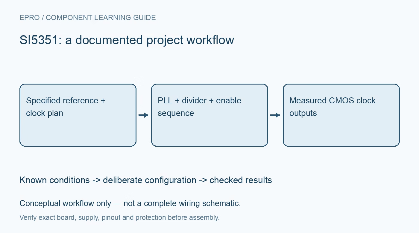
Choose a Si5351 variant, reference and output plan, then verify PLL updates, logic loading and measured clock frequency without assuming RF purity. This is a documentation-based project guide, not an independent hands-on test report.
1. Identify the Si5351 variant first
The Si5351 family is a programmable clock-generator family, not a single board with one universal pinout. Skyworks documents variants with different reference and control capabilities, and package options expose different outputs. Record the full ordering code, revision and carrier schematic before selecting a library. Define the required frequencies, output levels and connected loads. A common three-connector breakout does not establish the capabilities of every Si5351 family member. Manufacturer documentation.
2. Check the reference actually fitted
Inspect the crystal or external-reference arrangement and configure software for that exact source. A library default cannot correct a physically different reference frequency. Check the supported reference conditions and loading recommendations. Any reference frequency error propagates into the generated clocks, so a mathematically exact divider ratio does not guarantee an absolutely exact real-world output. Record reference calibration separately from the requested output frequency and the displayed software value. Manufacturer documentation.
3. Build a shared PLL and divider plan
Map each required output to the appropriate PLL and MultiSynth divider resources. Respect the device-specific frequency, divider and operating restrictions rather than assuming arbitrary settings are always equivalent. Consider whether changing one output also changes a shared resource used by another. A maintained configuration tool or library can calculate register values, but retain its version and generated plan. Test interacting outputs together, not merely one connector in isolation. Manufacturer documentation.
4. Make output enable and startup deliberate
Keep downstream circuitry in a safe state while configuring the generator. Follow the documented initialization and reset sequence, then enable only the intended outputs. Understand the distinction between software enable controls and any available hardware output-enable pin. Verify startup behavior after a complete power cycle. A receiver should not depend on a clock being valid before its source has stabilized or before firmware has established the requested configuration. Manufacturer documentation.
Newest in the store


5. Match logic levels and measurement loading
These are CMOS clock outputs, not inherently calibrated fifty-ohm RF signal-generator ports. Check the output supply domain, drive setting, permissible load and receiver thresholds. Use suitable probing and avoid attaching an unsuitable terminated instrument input directly. Poor probing can add ringing or distort the observed waveform. Keep the return path short and judge signal quality at the receiving circuit, not only at an unloaded breakout connector. Manufacturer documentation.
6. Verify changes rather than promising purity
Measure a modest output frequency with an appropriate counter or oscilloscope, accounting for the instrument timebase. Observe the behavior when frequencies change and when another output is enabled. Divider choices, reference quality, layout and loading influence the delivered clock. Do not claim a clean sine wave, specified phase noise or guaranteed glitch-free arbitrary retuning from the fact that a frequency command was accepted. Those properties require their own conditions and measurements. Manufacturer documentation.
7. Save a repeatable Si5351 configuration
Keep the exact part, reference, calibration, PLL mapping, divider settings, drive strength and enable sequence together. Compare requested frequency with measured frequency under the intended load, recording uncertainty rather than excessive digits. The related AD9833 article discusses a different signal-generation architecture and is not a wiring substitute. This guide is for controlled clock experiments; RF transmission or use in regulated equipment requires additional engineering and compliance beyond producing an oscillating output. Manufacturer documentation.
Related reading: AD9833 DDS: 7 Clock and Output-Load Checks.
Catalog note: The exact-part search did not return a matching Epro listing during preparation. Check the current catalog; this guide makes no availability, price or accessory claim.