


BQ25185 Charger: 7 Checks for a Compatible Power Path

BQ25185 Charger: 7 Checks for a Compatible Power Path
Plan BQ25185 charging with compatible cell chemistry, the correct ILIM/VSET configuration, charge current, input capability, temperature protection and thermal limits. This is a documentation-based planning guide, not a report of independent hands-on testing.
1. Match the BQ25185 to the cell
BQ25185 is a linear charger with power-path management and configurable settings for supported single-cell applications. Confirm the exact cell chemistry, charge voltage and permitted current before connecting a battery. Support for multiple chemistries does not mean the circuit identifies an unknown cell automatically. Obtain reliable battery specifications and retain independent suitable protection. Never charge damaged, swollen or unidentified cells, and stop evaluation if abnormal heating or physical damage appears. Manufacturer documentation.
2. Review the hardware configuration method
The documented ILIM/VSET arrangement selects associated input-current and battery-voltage settings. Use the manufacturer mapping for the actual component network rather than assuming two arbitrary independent controls or an I2C register configuration. Preserve the selected combination with the board revision and compatible battery identity. A resistor value that produces an acceptable current limit does not prove that the battery regulation voltage is also appropriate. Recheck both responsibilities whenever the hardware setting or cell changes. Manufacturer documentation.
3. Set charge current from battery and thermal limits
Use the documented ISET relationship and the cell specification to choose the intended charge current. Include component tolerance, source capability and thermal dissipation in the assessment. A headline maximum current is not a promise that any small carrier can deliver it continuously under every input voltage. Linear charging can dissipate substantial power. Do not repeatedly rely on thermal regulation as evidence that an otherwise unsuitable charging configuration is acceptable for the cell or board. Manufacturer documentation.
4. Analyze the input source and load together
Define input voltage range, available current, source impedance and system-load demand. Review the documented input regulation behavior for weak or high-impedance sources rather than assuming an advertised input rating guarantees the desired charge current. Power available to the system and battery is shared under the device’s control behavior. A low charge rate can reflect input or thermal limits rather than a firmware fault. Avoid describing input regulation as an unrestricted solution for every solar panel or unstable adapter. Manufacturer documentation.
Newest in the store


5. Preserve temperature and fault safeguards
Implement the documented temperature-sense and protective arrangements for the exact cell or pack. Do not bypass a temperature function merely to clear a status indication and make charging appear active. Keep charger control, battery protection and system safety responsibilities distinct. Analyze startup and absent-source conditions with the complete wiring. A charger feature list does not establish that every fault involving a battery, connector, enclosure or external power source has been adequately addressed. Manufacturer documentation.
6. Interpret power-path and status behavior
Review how the system output and battery path behave with input present, input removed and changing load demand. Use the documented status and control signals according to their actual roles. A charging indication is not a precision state-of-charge estimate, and a system rail that remains powered does not prove that the battery is receiving the intended current. Record source state, load conditions and relevant temperature or regulation context with every observed charging state. Manufacturer documentation.
7. Evaluate through protected supervised operation
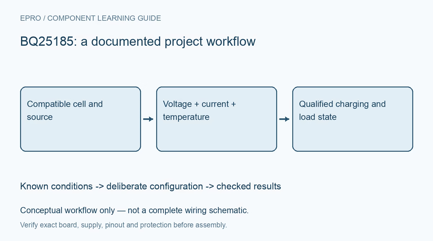
Retain cell specification, hardware settings, charge-current network, source capability, load profile, temperature arrangement and thermal conditions with results. Use suitable instruments and supervised procedures within battery limits, without deliberate abuse or uncontrolled fault injection. The related BQ24074 guide covers another charger configuration, not interchangeable resistor mappings. This BQ25185 workflow proposes documented compatibility checks and claims no independent charging-cycle measurements, universal source support or safety certification of a finished battery-powered product. Manufacturer documentation.
Related reading: BQ24074 Charger: 7 Design Checks for a One-Cell Power Path.
Catalog note: The exact-part search did not return a matching Epro listing during preparation. Check the current catalog; this guide makes no price, availability or included-accessory claim.