


ADS122U04 UART ADC: 7 Checks for a Valid Conversion Frame

ADS122U04 UART ADC: 7 Checks for a Valid Conversion Frame
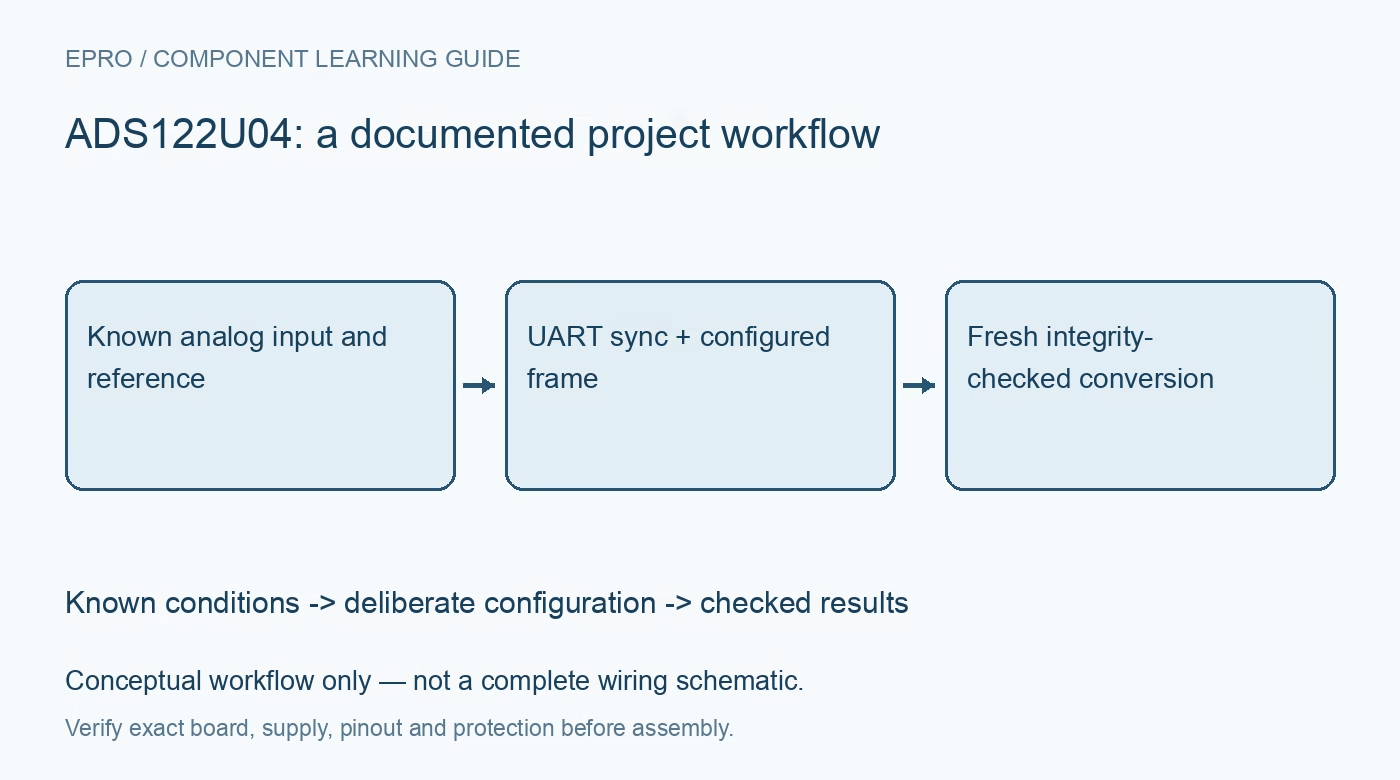
Build an ADS122U04 acquisition plan that checks UART synchronization, input limits, data ordering, optional counters and integrity fields before using ADC results. This is a documentation-based planning guide, not a report of independent hands-on testing.
1. Confirm that the interface really is UART
The ADS122U04 is a UART-interface converter; code for an SPI or I2C relative is not a drop-in driver. Confirm the full part number, schematic and logic-voltage compatibility before connecting the host. The serial connection is logic-level UART, not an RS-232 voltage interface. If the application requires isolation, provide an appropriate isolator and isolated power arrangement rather than treating a two-wire communications connection as an isolation barrier. Manufacturer documentation.
2. Bound both inputs and the reference
Define differential range, input common-mode voltage, gain and reference before wiring a signal. A small differential voltage alone does not establish that the PGA inputs remain within their allowed operating region. If the excitation current sources are used, check their compliance and the complete sensor-return path. The input multiplexer offers several selections, not four simultaneous converters. Record which physical input pair and reference belong to every reported channel. Manufacturer documentation.
3. Implement synchronization as a command requirement
The UART uses an eight-data-bit, no-parity, one-stop-bit format and an autobaud synchronization mechanism. The host must send the 55h synchronization word before each command as specified in the protocol. Treat synchronization and the following command as an intentional transaction, with a timeout and a recovery procedure. A driver that sends a sync byte only once at boot can appear to work during a limited trial while violating the required command sequence. Manufacturer documentation.
4. Define the byte layout before writing the parser
Conversion data are transmitted least-significant byte first. Optional features change the frame: the enabled data counter precedes the conversion bytes, while selected integrity information follows them. Make the parser depend on a verified configuration rather than a fixed three-byte assumption. Test its handling of partial reads, extra bytes and a restarted device. Decode the signed conversion only after locating the correct bytes; transport framing errors should never become believable analog measurements. Manufacturer documentation.
Newest in the store


5. Distinguish the available integrity modes
The integrity options are not all the same checksum. One setting appends inverted data; another uses a sixteen-bit CRC-CCITT field. When the conversion counter is enabled, it participates in the documented integrity calculation. Implement the exact configured mode, byte coverage and ordering from the manufacturer protocol. Include deliberate byte corruption in software tests. Reject failed frames and log the failure instead of quietly passing the previous result off as a successful new conversion. Manufacturer documentation.
6. Track freshness and input settling separately
The optional eight-bit counter advances with completed conversions and wraps from FFh to 00h. Handle that wrap explicitly when detecting repeated or missing results. Choose manual or automatic data-read behavior deliberately, and allow the analog path to settle after changing the multiplexer, gain, reference or excitation. A valid counter and CRC establish transport properties, not analog settling. Retain a channel identifier, configuration version and host timestamp beside the accepted conversion. Manufacturer documentation.
7. Qualify the path with known analog conditions
Begin with safe, bounded input conditions and an independently checked reference before connecting the final sensor. Exercise near-zero, positive and negative differential cases that remain inside all absolute and common-mode limits. Save raw UART frames, configuration and decoded values together. Repeat after a reset and after an intentionally interrupted transaction. Evaluate noise at the intended data rate rather than equating twenty-four output bits with twenty-four bits of usable resolution. Manufacturer documentation.
Related reading: ADS124S08 ADC: 7 Checks for a Settled Multiplexed Sensor Reading.
Catalog note: The exact-part search did not return a matching Epro listing during preparation. Check the current catalog; this guide makes no price, availability or included-accessory claim.