


LDC2114 Inductive Buttons: 7 Checks for a Repeatable Press

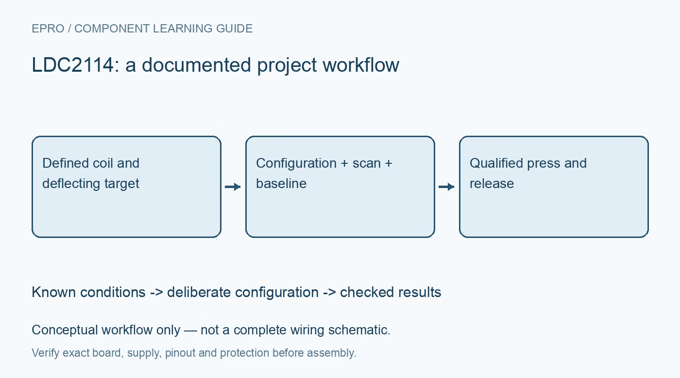
LDC2114 Inductive Buttons: 7 Checks for a Repeatable Press
Plan LDC2114 inductive buttons around the conductive target, narrow supply range, configuration mode and baseline behavior before treating counts as a press. This is a documentation-based planning guide, not a report of independent hands-on testing.
1. Define the mechanical sensing structure
The LDC2114 detects inductive changes associated with a conductive target and a resonant sensing arrangement. For an inductive button, the target’s small movement relative to the coil is part of the measurement. Document the coil, target material, gap, mounting stiffness and expected deflection before choosing thresholds. A nonmetal decorative front panel does not eliminate the need for a suitable conductive structure. Replacing that stack with an arbitrary enclosure can change the signal even when the electronics remain identical. Manufacturer documentation.
2. Check the narrow supply requirement
The device requires a nominal 1.8-volt supply with a narrow tolerance, rather than an unrestricted direct connection to a common 3.3-volt board rail. Verify the exact schematic, regulator and interface levels before powering a module. A breakout may include support circuitry, but its presence must be established rather than assumed. Include startup and host-reset conditions in the review. Keep bus pull-ups and logic connections compatible with the actual device domains throughout those transitions. Manufacturer documentation.
3. Use the required configuration-mode sequence
Enter configuration mode using CONFIG_MODE in the RESET register, then poll RDY_TO_WRITE before changing settings. Conversions stop while configuration mode is active; exit that mode to restart normal operation. Make this a deliberate driver state with timeouts and read-back checks, not a collection of unrelated writes. A device left in configuration mode may remain communicative while producing no fresh sensing activity. Record the complete approved register set and reapply it through the same controlled sequence after recovery. Manufacturer documentation.
4. Decode the documented data representation
The channel data use a twelve-bit two’s-complement representation split across an eight-bit low portion and four meaningful high bits. Reconstruct and sign-extend that field deliberately. Do not copy a wider conversion format from a different inductive-converter family. Preserve the raw bytes when comparing software versions. These processed counts and the dedicated button logic outputs serve different purposes; neither should be relabeled as calibrated force or distance without an independently justified mechanical model and validation. Manufacturer documentation.
Newest in the store


5. Match scan timing to the intended interaction
The available scan behavior depends on the selected mode and channel configuration. Decide how quickly a press must be recognized and how brief an interaction the application must capture. Then check the corresponding scan interval, host polling and interrupt or output handling together. Faster host reads cannot compensate for sensing that did not occur between scans. Test a short tap, a slow press and repeated operation, keeping the actual timing conditions in the qualification record. Manufacturer documentation.
6. Evaluate baseline tracking with held presses
Baseline tracking is useful for managing changing conditions, but its interaction with a slowly applied or sustained press needs deliberate review. Normal and low-power behavior can differ. Test the physical assembly through a long hold, release, wake-up and rearm sequence rather than assuming that a count threshold remains equivalent under every history. Document the selected tracking and button policies. If an application needs static force information, do not assume a touch-oriented baseline algorithm automatically provides that measurement. Manufacturer documentation.
7. Qualify press and release on the assembled panel
Exercise every channel on the final mechanical stack with representative mounting, temperature and user interaction. Include neighboring-channel activity, an obstructed mechanism and a supply interruption. Log raw counts, button state, scan configuration and the observed physical action. A claim of water insensitivity at the sensing principle does not certify the complete enclosure as waterproof or immune to all interference. The finished result should define a repeatable press-and-release decision for this assembly, with the remaining mechanical and environmental limits stated clearly. Manufacturer documentation.
Related reading: FDC2214 Capacitive Sensor: 7 Checks Before Reporting Capacitance.
Catalog note: The exact-part search did not return a matching Epro listing during preparation. Check the current catalog; this guide makes no price, availability or included-accessory claim.