


ADS1262 Precision ADC: 7 Checks Before Trusting 32-Bit Data

ADS1262 Precision ADC: 7 Checks Before Trusting 32-Bit Data
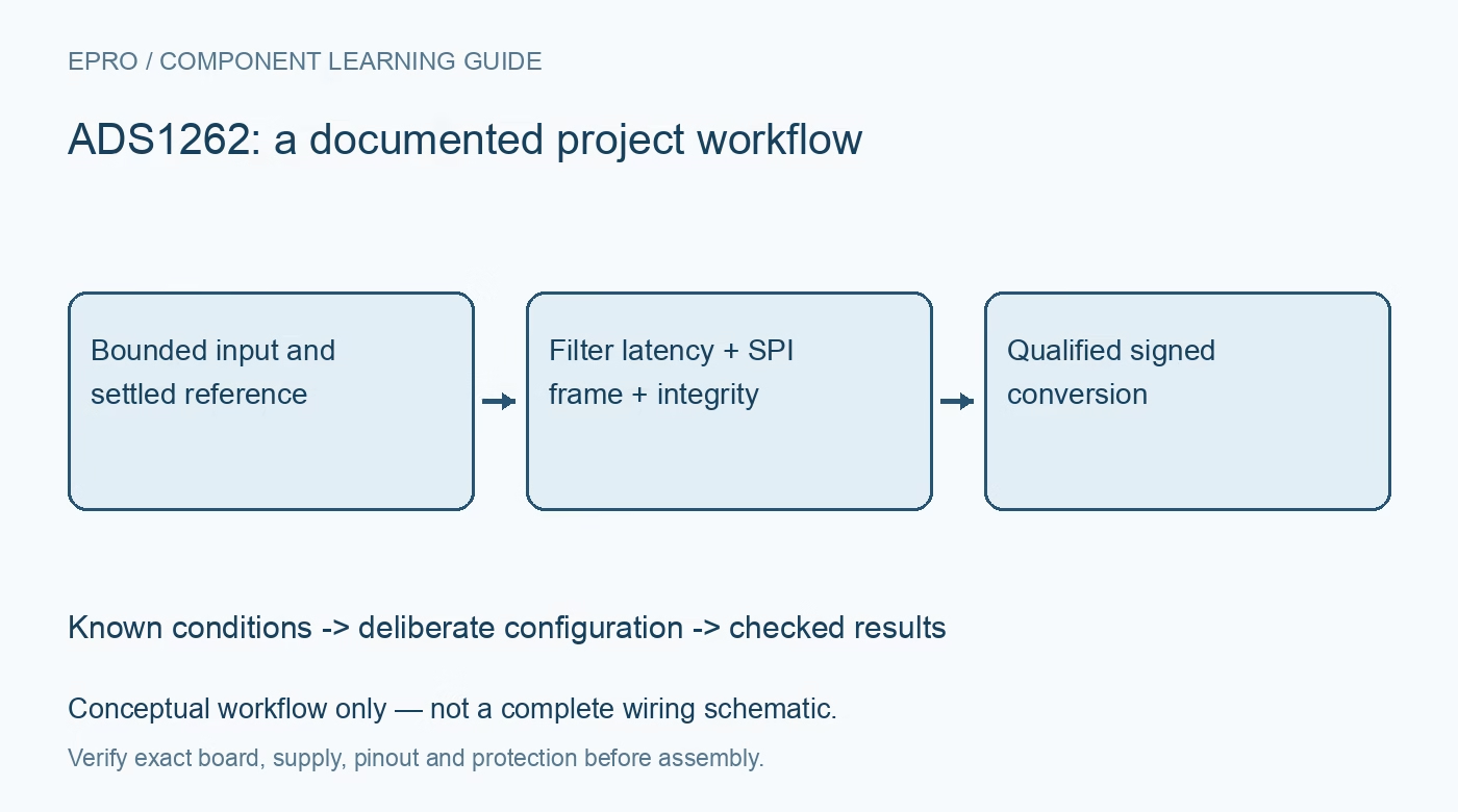
Plan an ADS1262 acquisition path around analog headroom, filter latency, four-byte results and the selected integrity mode before treating codes as measurements. This is a documentation-based planning guide, not a report of independent hands-on testing.
1. Separate the ADS1262 from the ADS1263
The family datasheet describes both devices, but the auxiliary twenty-four-bit ADC belongs to the ADS1263. Do not build an ADS1262 acquisition plan around that additional converter. Identify the exact device, supply arrangement and board schematic before choosing a driver. The multifunction analog pins also do not represent eleven simultaneous measurement channels. Document which multiplexer selection, reference and excitation configuration belong to each intended observation, especially when borrowing examples written for the other family member. Manufacturer documentation.
2. Establish analog headroom before selecting gain
Define differential input range, common-mode voltage, PGA gain and reference together. A small differential signal is not enough to establish valid amplifier operation if either input violates the operating region. Include the sensor excitation and return path when checking compliance. Use protected, bounded test inputs during initial validation. The internal reference and excitation sources simplify some circuits, but they do not eliminate reference settling, input protection, source impedance or layout requirements in the assembled measurement chain. Manufacturer documentation.
3. Distinguish sample rate from first-result latency
The digital filter selection affects both interference rejection and conversion latency. After changing channels, follow the documented conversion restart behavior and wait for a settled result rather than simply delaying one nominal sample period. The manufacturer latency guidance assumes the analog input has already settled before conversion starts. Add the real sensor and external-filter settling requirements separately. Keep channel-switch timing in the record so a valid-looking result from a transition is not mistaken for a settled measurement. Manufacturer documentation.
4. Decode the four-byte signed conversion correctly
The primary conversion result is thirty-two-bit two’s complement, transmitted most-significant bit first. Reconstruct all four bytes before applying signed scaling. A driver inherited from a twenty-four-bit converter can silently discard useful bits or misplace the sign. Test the decoder with documented positive, negative and zero examples, then check host integer and floating-point behavior. Preserve the original bytes alongside engineering units while bringing up the system so transport and scaling errors remain distinguishable. Manufacturer documentation.
Newest in the store


5. Match the parser to the selected interface fields
Optional status and integrity fields change the returned data sequence. Read back the interface configuration and make frame length an explicit driver setting instead of guessing from received bytes. Include the documented serial timing, chip-select behavior and data-ready handling in the implementation review. A complete transfer is not automatically a fresh conversion. Tag accepted data with the configuration and channel identity used for that conversion, and reject interrupted or unexpectedly short frames rather than manufacturing a result. Manufacturer documentation.
6. Implement checksum or CRC as distinct modes
The optional checksum byte and CRC byte are different integrity mechanisms. In checksum mode, the converter adds the conversion bytes and the documented 9Bh offset, retaining the low eight bits. CRC mode instead uses the specified CRC-8 polynomial procedure. Follow the exact selected algorithm and byte coverage; the integrity byte is not supplied on ordinary register reads. Test deliberately corrupted conversion frames and document recovery. Neither mechanism proves analog accuracy or correct reference selection. Manufacturer documentation.
7. Qualify resolution with a repeatable measurement record
Compare bounded known inputs at the intended gain, filter and data rate. Save raw frames, status, reference conditions, timestamps and the accepted result together. Include a reset, input-channel change and communication interruption in the qualification plan. Measure noise and drift under representative conditions rather than equating a thirty-two-bit output word with thirty-two usable accuracy bits. The final result should show which observations were fresh, settled and correctly decoded, with the remaining measurement limitations stated clearly. Manufacturer documentation.
Related reading: ADS122U04 UART ADC: 7 Checks for a Valid Conversion Frame.
Catalog note: The exact-part search did not return a matching Epro listing during preparation. Check the current catalog; this guide makes no price, availability or included-accessory claim.