


TPS25947 eFuse: 7 Checks for Variant, Inrush and Fault Policy

TPS25947 eFuse: 7 Checks for Variant, Inrush and Fault Policy
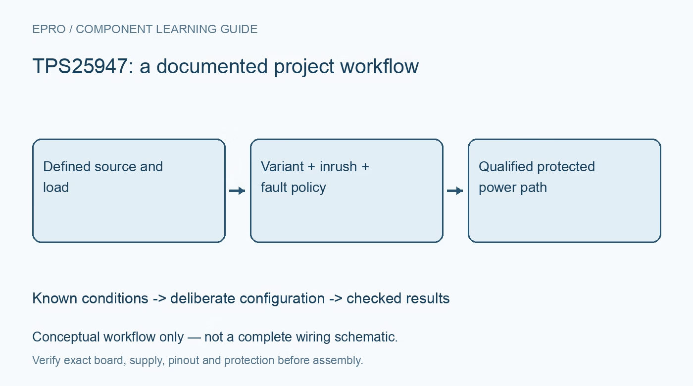
Choose the correct TPS25947 eFuse variant, then check current-limit policy, inrush timing, reverse blocking and ready signals on a protected low-voltage setup. This is a documentation-based planning guide, not a report of independent hands-on testing.
1. Select behavior from the full orderable number
TPS25947 is a family, not one universal protection policy. The comparison table distinguishes TPS259470 active-current-limit devices with adjustable overvoltage cutoff, TPS259472 active-current-limit devices with selectable overvoltage clamp, and TPS259474 circuit-breaker devices with adjustable cutoff. The A and L options also distinguish automatic retry and latch-off responses. Record the complete suffix before designing firmware or a fault indicator. The wrong family assumption can change both the electrical response and the meaning of a pin. Manufacturer documentation.
2. Keep the application inside a protected low-voltage envelope
The recommended input operating range is 2.7 V to 23 V; absolute maximum and reverse-polarity withstand figures are separate ratings with specific conditions. Do not use an absolute maximum as a normal setpoint. Define source voltage, load current, wiring and upstream protection before energizing the board. Use a current-limited supply and bounded loads for qualification. This guide is not an instruction to apply destructive faults, defeat upstream protection or perform hazardous high-energy testing. Manufacturer documentation.
3. Distinguish current limiting from breaking the circuit
Active-current-limit variants constrain current according to their documented policy, whereas circuit-breaker variants interrupt the path after the applicable threshold and timing conditions. Set ILIM using the relevant datasheet procedure and include resistor tolerance and device accuracy. The programmable range does not establish the safe continuous current of a particular PCB. Consider connectors, copper, thermal conditions and the load together. Document the intended response rather than assuming every overload results in the same regulated-current waveform. Manufacturer documentation.
4. Coordinate inrush control and transient timing
The output ramp and load capacitance determine startup demand, while the transient blanking arrangement affects overload qualification. Select the dVdt and timing components through the documented equations and limits, including startup safe-operating-area considerations. A longer timer is not a universal cure for a load that exceeds the design envelope. Observe normal startup with a representative capacitive load and a bounded source. Keep the ramp configuration, capacitance and ambient conditions in the qualification record for later revisions. Manufacturer documentation.
Newest in the store


5. Choose overvoltage clamp or cutoff deliberately
A clamp and an overvoltage cutoff produce different load behavior. For TPS259472, the selectable clamp levels are defined family settings; for applicable other variants, the adjustable OVLO network establishes the cutoff threshold. Check tolerances and downstream voltage ratings before selecting either approach. Do not infer a regulated supply replacement from a protection feature. Evaluate the intended operating transitions within safe source limits, using the exact variant documentation rather than a generic eFuse diagram or another suffix’s application schematic. Manufacturer documentation.
6. Interpret monitoring pins by variant
The family reuses functions across package pins: the comparison table identifies AUXOFF and FLT for TPS259470, versus PG and PGTH for other listed variants. Confirm the actual pinout and suitable pull-up arrangements before attaching host inputs. Current monitoring also has scaling and loading requirements that must be respected. A ready indication is not a full system safety verdict. Keep monitor readings, protection state and host reset behavior as separate signals in the software model and test record. Manufacturer documentation.
7. Verify recovery without bypassing protection
The integrated back-to-back FET arrangement provides documented reverse-current blocking, but does not make the whole assembly an independently certified protection system. Verify normal startup, shutdown and permitted recovery behavior with bounded conditions and suitable instrumentation. Record whether the selected device retries automatically or requires the documented latch-off reset sequence. Investigate unexpected trips instead of removing limits. Preserve source, load, component values and measured temperatures so the design can be reviewed without relying on an unexplained pass indicator. Manufacturer documentation.
Related reading: BQ25895 Charger: 7 Checks for the Real Input-Current Limit.
Catalog note: The exact-part search did not return a matching Epro listing during preparation. Check the current catalog; this guide makes no price, availability or included-accessory claim.