


ADS131E08 ADC: 7 Checks for Rate-Dependent Frame Length

ADS131E08 ADC: 7 Checks for Rate-Dependent Frame Length
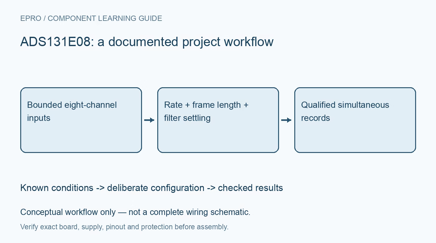
Plan ADS131E08 simultaneous acquisition with the correct rate-dependent word length, channel slots, reference settings, settling time and serial readout budget. This is a documentation-based planning guide, not a report of independent hands-on testing.
1. Define eight safe analog paths before enabling conversion
ADS131E08 provides eight simultaneous differential acquisition channels, not an isolated interface for direct connection to power wiring. Specify attenuation, protection, bias and isolation outside the ADC as required. Check each input pin against the analog supply and PGA operating limits, not only the differential signal amplitude. Record analog and digital supply choices, reference source and clock. Use protected low-voltage sources for initial tests; an energy-metering application example does not make exposed mains experimentation safe. Manufacturer documentation.
2. Store gain and reference beside each channel result
The transfer function depends on reference voltage and programmable gain. A signed code alone is insufficient to reconstruct the physical input later. Confirm the enabled channel settings, differential polarity and actual reference configuration, then preserve those choices in the acquisition record. Internal test sources can help distinguish a serial or configuration problem from an external analog problem, but they do not validate the complete sensor chain. Check external filter balance and input headroom at every selected gain. Manufacturer documentation.
3. Change the parser when the data rate changes
This family does not transmit twenty-four data bits per channel at every rate. For ADS131E08 at 32 kSPS and 64 kSPS, the frame contains twenty-four status bits plus eight sixteen-bit channel words, totaling 152 bits. At the other documented rates it contains twenty-four status bits plus eight twenty-four-bit words, totaling 216 bits. Couple the parser length to the actual rate register. A fixed twenty-seven-byte parser can silently corrupt high-rate acquisition rather than merely reducing precision. Manufacturer documentation.
4. Preserve channel positions even when channels are disabled
The manufacturer specifies that a powered-down channel returns zero in its existing slot; the output sequence does not shrink around it. Retain the full channel map and distinguish a disabled-channel zero from a measured zero. Decode each active word as signed twos complement at the selected resolution. Check the status field independently rather than shifting every field until the data look plausible. Synthetic frames containing distinct channel patterns are useful for testing software before connecting real sensors. Manufacturer documentation.
Newest in the store


5. Budget serial transfer against DRDY and command rules
DRDY indicates that conversion data are ready, while the chosen continuous-read or command-driven mode determines how they are retrieved. Calculate the required SCLK rate from frame size, data rate and transaction overhead, including host latency. Follow the command-decoding and register-access timing requirements; do not assume any opcode can be inserted into a continuous-read stream. Detect missed acquisition deadlines explicitly. Reading a status-looking prefix successfully is not proof that all eight channel words belong to the same intended record. Manufacturer documentation.
6. Respect settling and recalibration after configuration changes
Startup settling depends on clock and decimation settings. A step in an already running input also passes through the digital filter, so immediate samples can represent filter history rather than the final signal. Use the documented settling rules to qualify records after start, rate or gain changes. The manufacturer recommends offset calibration after changing PGA gain; account for that process and its timing. Do not treat a completed SPI transaction as evidence that the analog path and filter have settled. Manufacturer documentation.
7. Validate channel coherence with controlled test signals
Begin with the internal test facilities and bounded external inputs, then compare repeated channel records at both a twenty-four-bit rate and a sixteen-bit high-rate setting. Check polarity, frame length, disabled slots, missed-DRDY handling and restart behavior. Save register snapshots, clock frequency and parser version with the results. Simultaneous sampling is valuable, but board filtering, source mismatch and digital timing still affect a system measurement. No independent noise, isolation or power-quality performance is claimed by this documentation-based guide. Manufacturer documentation.
Related reading: ADS131M02 ADC: 7 Checks for Settled Two-Channel Samples.
Catalog note: The exact-part search did not return a matching Epro listing during preparation. Check the current catalog; this guide makes no price, availability or included-accessory claim.