


TCA9536 GPIO Expander: 7 Checks for P3 Interrupt and Soft Reset

TCA9536 GPIO Expander: 7 Checks for P3 Interrupt and Soft Reset
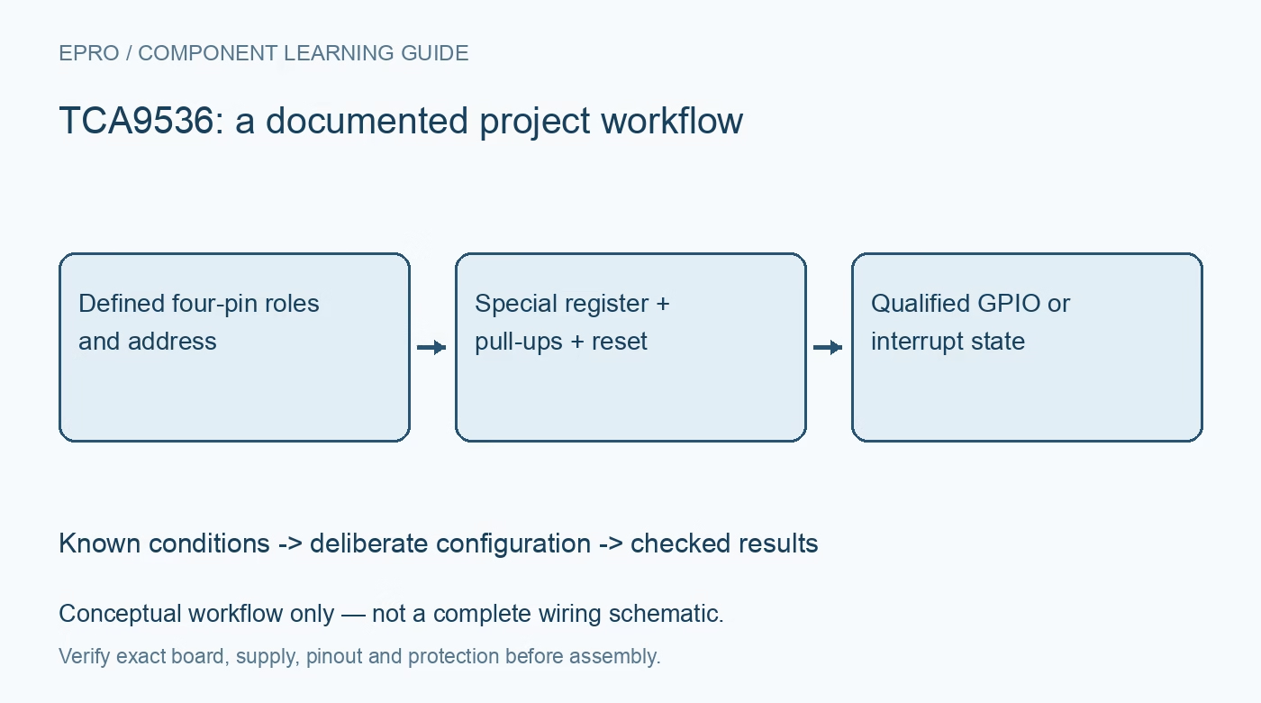
Configure TCA9536 GPIO with seven checks for fixed addresses, register 0x50, switchable pull-ups, P3 interrupt use, safe output startup and general-call reset. This is a documentation-based planning guide, not a report of independent hands-on testing.
1. Verify the suffix and package pin map
TCA9536 is a four-bit I2C expander with a fixed address rather than external address-selection pins. The unsuffixed device uses seven-bit address 0x41, while A, B and C address variants differ. Check the installed ordering code before writing an address constant. Also compare the exact package drawings: small packages should not be treated as interchangeable pin-for-pin by appearance. Keep supply range, controller logic levels and bus pull-ups in the initial schematic review. Manufacturer documentation.
2. Prepare output values before changing direction
At power-up, the ports are configured as inputs. Establish the intended output-register values before enabling selected output drivers, especially when pins control resets or subsystem enables. Configuration bits use one for input and zero for output. The input, output, polarity and configuration registers occupy the familiar low addresses, but familiar organization is not proof that a driver for a different expander supports every function. Preserve unused bits according to the register descriptions. Manufacturer documentation.
3. Treat register 0x50 as a separate function
The additional special-function register is at 0x50, not the next sequential byte after the basic configuration register. It controls the P3 interrupt override and internal pull-up disabling. Access it explicitly rather than including it in an assumed linear burst. Verify the command byte and written mask in a bus trace, then read back the configuration. An incorrect special-register address may leave basic GPIO working while the intended interrupt or low-power behavior never becomes active. Manufacturer documentation.
4. Choose GPIO P3 or interrupt P3 deliberately
P3 can operate as the fourth GPIO or be repurposed as the open-drain interrupt output. That override consumes the pin; the circuit cannot simultaneously use P3 as an ordinary driven control signal and an independent interrupt wire. Review external connections before changing the special-function bit. Define how the remaining inputs will generate change indications and how the host services them. An interrupt reports a changed input condition, not a queue of precisely timestamped transitions. Manufacturer documentation.
Newest in the store


5. Include pull-up disabling in the electrical design
Internal port pull-ups are enabled by default and can be disabled through the special-function register. The disable setting applies to the port pull-ups collectively, including P3 when used as INT. Provide an appropriate external interrupt pull-up when the chosen configuration requires it, and retain separate I2C pull-ups on SDA and SCL. Estimate current through switches or devices that hold a pulled-up pin low. Do not assume changing direction alone removes every internal bias path. Manufacturer documentation.
6. Review the bus-wide impact of software reset
The reset sequence uses the general-call address byte 0x00 followed by data 0x06 and a STOP. Other devices supporting the same command can also reset, so evaluate the entire bus before using it as a local recovery shortcut. The bus must already be operational; a command cannot repair a target holding communication lines stuck. Reset restores defaults, which can change pin behavior. Reapply reviewed latch, direction and special-function settings before treating the subsystem as ready. Manufacturer documentation.
7. Test interrupt service and reset recovery together
Exercise distinct input patterns, output changes and P3 role selection with the actual external circuit. Record register values and INT before and after input reads, then test the documented reset sequence only where its bus-wide consequences are acceptable. Verify that output-controlled equipment remains safe during reinitialization. A register acknowledgment proves a communication event, not correct load voltage or a complete event history. Preserve diagnostic reads and host state so missed transitions or unexpected defaults can be investigated. Manufacturer documentation.
Related reading: TCA9554 GPIO Expander: 7 Checks for Pull-Ups and Interrupts.
Catalog note: The exact-part search did not return a matching Epro listing during preparation. Check the current catalog; this guide makes no price, availability or included-accessory claim.