


TPS22950 Load Switch: 7 Checks for Current Limits and Fault Meaning

TPS22950 Load Switch: 7 Checks for Current Limits and Fault Meaning
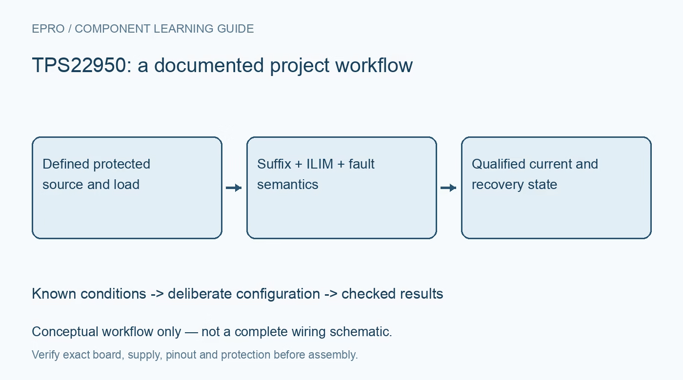
TPS22950 checks for suffix-dependent ratings, ILIM programming, fault-pin meaning, reverse blocking and thermal recovery. This is a documentation-based planning guide, not a report of independent hands-on testing.
1. Preserve the full suffix when selecting ratings
The TPS22950 family does not give every suffix identical behavior. The base device has a 2.7 A maximum continuous-current rating under its specified conditions, while the C variant has a 3.2 A rating. The L variant uses different fault-recovery behavior and lacks reverse-current blocking. An adjustable current-limit range reaching 3.5 A is not permission to run the base part continuously at 3.5 A. Record the complete ordering code before choosing copper, connectors, protection thresholds and load startup assumptions. Manufacturer documentation.
2. Define the input and load operating envelope
The recommended input range is 1.8 V to 5.5 V. ON is an active-high control and should have an intentional state rather than a floating connection. Define normal load current, inrush demand, downstream capacitance and possible externally powered outputs. Include supply droop and connector resistance in the plan. Use a protected low-voltage fixture with a current-limited source and bounded electronic or resistive load. A short-circuit headline does not justify uncontrolled fault demonstrations on an unprotected board. Manufacturer documentation.
3. Program ILIM with the correct units
The nominal relation is ILIM in amperes = 1.18 times RILIM in kilohms raised to the power minus 1.072. A 1 kilohm resistor therefore corresponds to approximately 1.18 A nominal. The resistor connects from ILIM to ground; verify the exact implementation against the application circuit. Apply electrical-table limits and resistor tolerance rather than treating the typical equation as a calibrated threshold. Keep the programmed limit distinct from the package continuous-current capability and the upstream source rating. Manufacturer documentation.
4. Expect limiting dynamics rather than an ideal clamp
During overcurrent, the base device can enter constant-current regulation with a reduced output voltage. Current can overshoot before the documented limiting response has taken effect, so downstream components still need an appropriate transient budget. Dissipation rises when substantial voltage appears across the switch while current flows. Observe current and output voltage together under a bounded load step. A slow meter may hide a short peak, and one steady-state limited reading does not establish safe behavior for every startup waveform. Manufacturer documentation.
Newest in the store


5. Do not interpret FLT high as no current limiting
FLT is open-drain and requires a compatible pull-up if monitored. The base device fault table allows FLT to remain high-impedance during an ordinary output short or current-limiting condition; it reports the specified thermal and reverse-current fault states instead. Consequently a pulled-high fault pin is not proof that the load is receiving an unrestricted normal supply. Preserve this distinction in firmware names and logs. If the application needs to detect current limiting directly, provide suitable additional observation rather than inferring it from FLT alone. Manufacturer documentation.
6. Review reverse blocking and recovery by variant
The base and C variants provide the documented reverse-current-blocking function, including disabled operation, while the L variant does not. Blocking has finite thresholds, response time and leakage; it is not an instantaneous zero-current ideal diode. The base device can automatically recover after thermal shutdown, whereas the L variant has different latched behavior. Confirm the actual suffix before specifying a recovery procedure. Repeated shutdown and restart under a persistent overload is not acceptable normal regulation and can repeatedly disturb the downstream system. Manufacturer documentation.
7. Validate load behavior and protection independently
Record the full part code, ILIM resistor, rail voltages, load waveform, current, FLT level and temperature. Check startup, a bounded overload, load removal and any expected output-backdrive scenario within a reviewed fixture. Compare observations with specified tolerances and timing conditions. Keep upstream fusing and independent system safety requirements separate from this switch checklist. A useful acceptance record explains whether the output is enabled, current-limited, reverse-blocked or thermally recovering instead of reducing every condition to one generic fault bit. Manufacturer documentation.
Related reading: TPS22810 Load Switch: 7 Checks for UVLO and Discharge Limits.
Catalog note: The exact-part search did not return a matching Epro listing during preparation. Check the current catalog; this guide makes no price, availability or included-accessory claim.