


TPS7A90 Low-Noise LDO: 7 Checks for Soft-Start and Final Settling

TPS7A90 Low-Noise LDO: 7 Checks for Soft-Start and Final Settling
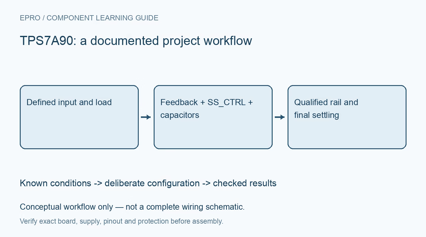
Plan TPS7A90 regulation with valid headroom, SS_CTRL selection, NR/SS capacitance, output stability and qualified final settling. This is a documentation-based planning guide, not a report of independent hands-on testing.
1. Define the rail and the actual load envelope
TPS7A90 is an adjustable low-noise LDO capable of sourcing 500 mA under suitable conditions. Its recommended input range is 1.4 V to 6.5 V and its adjustable output range is 0.8 V to 5.7 V. Choose an operating point that satisfies both ranges and preserves regulation headroom. Include load startup, transient demand and ambient temperature in the plan; the current headline does not override thermal or dropout constraints. Manufacturer documentation.
2. Calculate the feedback network and error budget
Set the output using the documented external resistor-divider relationship and reference value. Include resistor tolerance, leakage, regulator accuracy and temperature effects when predicting the final rail. Route the feedback node away from switching noise and load-current returns. Verify the actual divider values before power-up rather than relying on a module label. An ideal calculated voltage is a design target, not evidence that the assembled output has been calibrated or independently measured. Manufacturer documentation.
3. Preserve dropout margin under the worst input dip
Compare the relevant dropout specification with load current, output voltage and temperature conditions. The advertised low dropout is not one guaranteed value for every rail. Evaluate cable loss and upstream converter ripple at peak demand. Dissipation is approximately the input-to-output voltage difference multiplied by output current, with device consumption added. A regulator can have ample electrical headroom and still overheat, or remain cool while an input dip temporarily pushes it out of regulation. Manufacturer documentation.
4. Select SS_CTRL with the NR/SS capacitor
The noise-reduction capacitor also controls startup. Grounding SS_CTRL selects a typical 6.2 microamp charging current, while connecting SS_CTRL to IN selects a typical 100 microamp current. Use the appropriate limits and capacitor tolerance when budgeting startup. If no NR/SS capacitor is fitted, the manufacturer requires SS_CTRL at ground to avoid output overshoot. Do not copy a faster-charge connection without checking whether the corresponding capacitor actually exists on the board. Manufacturer documentation.
Newest in the store


5. Allow for the final settling tail
The startup current source switches off when the feedback approaches approximately 97 percent of the reference. The remaining portion charges through the internal noise-reduction resistance, creating a slower RC tail that matters with a large NR/SS capacitor. A rail that looks almost correct on an oscilloscope may not yet meet a precision requirement. Define an allowable voltage error and a measurement time rather than equating visible startup completion with final analog accuracy. Manufacturer documentation.
6. Qualify capacitors and power-good interpretation
Use the required effective output capacitance and layout from the datasheet, accounting for ceramic capacitor DC-bias loss and temperature. Feed-forward and noise-reduction components can influence transient behavior and startup. The open-drain PG signal needs a compatible pull-up and should be interpreted using its documented threshold and timing. A digital PG transition does not measure integrated output noise or certify final reference settling. Keep those analog requirements as separately checked acceptance criteria. Manufacturer documentation.
7. Verify the rail with the intended measurement bandwidth
Observe startup, load steps, disable and supply collapse with the actual capacitor network. Measure small noise using an appropriate low-noise setup and stated bandwidth; a general-purpose scope trace cannot substantiate the datasheet microvolt figure by itself. Record input voltage, load, SS_CTRL state, capacitor values and temperature. Check any externally driven output against device limits before testing. This documentation-based workflow proposes verification steps and does not claim that a particular board has passed them. Manufacturer documentation.
Related reading: TPS7A91 Low-Noise LDO: 7 Checks for Soft Start and Power-Good Timing.
Catalog note: The exact-part search did not return a matching Epro listing during preparation. Check the current catalog; this guide makes no price, availability or included-accessory claim.