


THVD1520 RS-485 Transceiver: 7 Checks for 10Mbps Bus Integrity

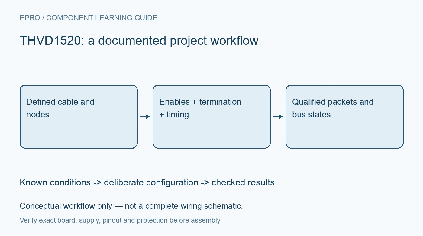
THVD1520 RS-485 Transceiver: 7 Checks for 10Mbps Bus Integrity
Review THVD1520 5V interfaces, 10Mbps timing, termination, bus voltage limits, failsafe states and realistic protection requirements. This is a documentation-based planning guide, not a report of independent hands-on testing.
1. Define a half-duplex link rather than a protocol
THVD1520 is a half-duplex RS-485 transceiver rated for signaling up to 10 Mbps under documented conditions. It translates the host data and bus electrical levels; it does not add packet validation, addressing or collision management. Map D, R, DE, active-low RE, A and B against the actual package and connector. Establish one consistent line-polarity convention across nodes because connector labels and naming conventions can differ between finished products. Manufacturer documentation.
2. Provide five volts and qualify MCU compatibility
The recommended supply range is 4.5 V to 5.5 V. Check controller outputs against guaranteed D and enable input thresholds, then separately check whether the controller receiver pin tolerates the transceiver R output. A 3.3 V controller being able to drive an input does not prove the opposite direction is safe. Account for startup, disabled states and any level translator timing. Do not operate the transceiver from 3.3 V simply because the host uses that logic rail. Manufacturer documentation.
3. Budget the complete transmit-turnaround sequence
DE high enables the driver, while active-low RE low enables the receiver. Decide whether local receive remains active during transmit and handle any echo intentionally. When releasing the line, use UART transmission-complete status rather than a software-buffer-empty indication. Include transceiver enable and disable delays, controller latency and remote response timing. At higher bit rates, a small turnaround error can damage the start or end of a frame even when steady repetitive data appears correct. Manufacturer documentation.
4. Match the cable and termination to edge behavior
Place the intended termination at the physical bus ends and keep node stubs appropriate for the cable and signal transitions. Ten-megabit capability does not guarantee operation over an arbitrary cable length or star topology. Include connector discontinuities, bias networks and all node capacitance in the design review. The one-eighth-unit-load receiver specification concerns DC loading and does not independently establish a maximum practical network size at the chosen data rate and wiring geometry. Manufacturer documentation.
Newest in the store


5. Use this device’s bus voltage limits
The recommended voltage at either bus terminal is from negative 7 V to positive 12 V with respect to local ground. Do not copy the wider operating common-mode claim of a different THVD variant. Absolute stress limits and IEC transient tests are separate categories from sustained operating voltage. Calculate local ground shifts and line excursions together. The device does not provide galvanic isolation, and its integrated ESD protection does not make every installation immune to surge or wiring faults. Manufacturer documentation.
6. Treat failsafe as defined logic, not successful communication
Open, short and idle-bus failsafe behavior helps establish a receiver output when the differential input is absent or inadequate. That does not prove cable continuity, correct polarity or the presence of a functioning remote node. Add packet integrity checks, sequence handling and timeouts at the application layer. Preserve errors and invalid intervals instead of interpreting an idle level as a valid reading. Evaluate any external biasing together with termination and driver load. Manufacturer documentation.
7. Verify packets and waveforms on the assembled bus
Start with two nodes and a known cable, then increase traffic rate and add representative branches or nodes gradually. Observe differential amplitude, common mode, DE timing and UART framing with suitable instruments. Exercise reset, unplugging and loss of one node’s power under controlled conditions. Record cable, topology, termination, supply and error counts. A datasheet maximum or a single successful packet cannot establish long-term reliability, immunity or universal range for a deployed network. Manufacturer documentation.
Related reading: THVD1510 RS-485 Transceiver: 7 Checks for 5V Logic and Bus Control.
Catalog note: The exact-part search did not return a matching Epro listing during preparation. Check the current catalog; this guide makes no price, availability or included-accessory claim.