


TPS22966 Load Switch: 7 Checks for Two Controlled Rails

TPS22966 Load Switch: 7 Checks for Two Controlled Rails
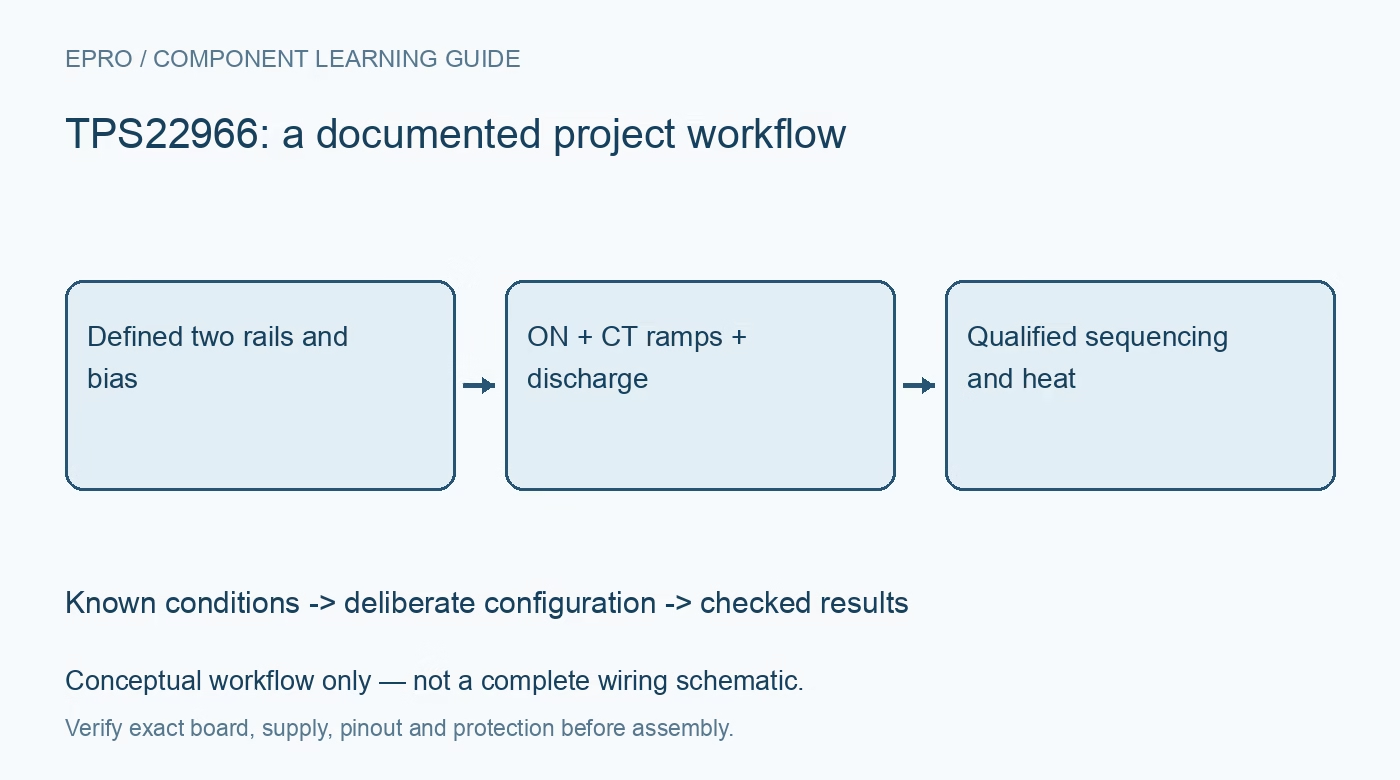
Plan TPS22966 dual-rail switching with shared bias, individual ramp capacitors, output discharge and combined thermal limits. This is a documentation-based planning guide, not a report of independent hands-on testing.
1. Identify the exact dual-channel variant
TPS22966 provides two independently controlled load switches, each with its own input, output, ON control and timing-capacitor connection. The standard device includes quick output discharge, while related ordering variants can differ. Verify the full device name, package and schematic rather than assuming every family member handles the off state identically. Separate channel behavior from package behavior: independent controls do not create independent thermal environments or remove the consequences of sharing the same board return and bias rail. Manufacturer documentation.
2. Meet the shared bias requirement on both channels
The bias rail is specified from 2.5 V to 5.5 V, and the recommended VIN range is 0.8 V up to VBIAS. This relationship is more precise than reading the headline input range alone. Check both inputs against the actual shared bias during startup, shutdown and partial-power operation. Resistance figures quoted at a five-volt bias do not automatically apply at a lower bias. Record the worst rail relationship before accepting a low-voltage switching design. Manufacturer documentation.
3. Calculate two ramps rather than one assumed delay
CT1 and CT2 independently shape the output rise times. Use the documented capacitor relationship and conditions to choose each ramp, then estimate the associated capacitive inrush from the load capacitance and voltage slope. Timing capacitors shape an analog transition; they are not programmable digital delay guarantees. Include capacitance tolerance, input stiffness and loads that start drawing current during the ramp. Deliberate sequencing requires enough separation to tolerate those variations, not just nominally different capacitor values. Manufacturer documentation.
4. Account for quick discharge when a rail turns off
The standard TPS22966 includes an approximately 220-ohm quick-output-discharge path. That path helps remove stored output charge when the switch is disabled, but it also matters if another source keeps the output powered. Do not interpret ON low as an unrestricted isolated connection. Review back-powered loads, interconnections between the two rails and the discharge energy in output capacitors. Confirm the exact variant before using the off-state behavior in a power-sharing or external-supply arrangement. Manufacturer documentation.
Newest in the store


5. Evaluate combined conduction loss and package temperature
The maximum continuous rating is six amperes per channel under applicable conditions. It is not an unconditional promise of twelve amperes through any small breakout board. Estimate each channel loss using the relevant on-resistance over bias and temperature, then add the losses that heat the shared package. Include copper, thermal-pad implementation and ambient conditions. A low typical resistance can still produce important heating at high current, and channel interaction may appear thermally even when their electrical controls are independent. Manufacturer documentation.
6. Define ON states during partial power and reset
The active-high ON inputs need defined voltages throughout the supply sequence. Verify logic thresholds and permitted control levels separately from VIN and VBIAS. Establish what the controller does before its firmware configures the pins and after a brownout. Exercise the case where one load remains powered while the other rail and bias change state. This device is a controlled switch, not a substitute for a separately designed current limiter, fault disconnect or complete reverse-power protection system. Manufacturer documentation.
7. Qualify startup, shutdown and restart as a sequence
Start with current-limited sources and representative output capacitances, checking each channel separately before enabling both. Record input voltage, bias, output ramp and load behavior during startup and rapid restart. Confirm that discharge and residual load voltage do not corrupt the intended second startup. Observe temperature at the actual sustained current rather than inferring it from a nominal rating. These are planning checks from manufacturer documentation, not a claim that this guide independently tested a dual-rail assembly. Manufacturer documentation.
Related reading: TPS22968 Dual Load Switch: 7 Checks for Shared Bias and Rail Sequencing.
Catalog note: The exact-part search did not return a matching Epro listing during preparation. Check the current catalog; this guide makes no price, availability or included-accessory claim.