


ADS131M06 ADC: 7 Checks for Six-Channel Phase Records

ADS131M06 ADC: 7 Checks for Six-Channel Phase Records
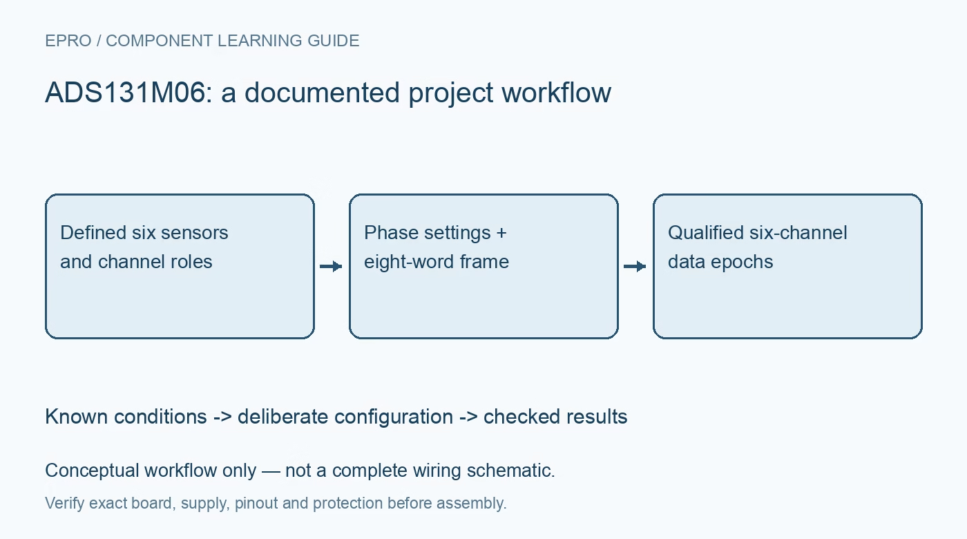
Prepare ADS131M06 six-channel records with an eight-word SPI frame, signed phase settings, gain metadata and explicit recovery flags. This is a documentation-based planning guide, not a report of independent hands-on testing.
1. Define all six signal-chain roles before configuration
ADS131M06 simultaneously samples six differential channels with programmable gain and a documented data-rate capability up to thirty-two kilosamples per second. Build a channel table containing sensor type, electrical range, gain and intended phase relationship. In a power-measurement application, a voltage divider and a current transformer can introduce different errors even though the converter samples simultaneously. The device supplies measurement functions, not mains isolation. Establish safe input conditioning and protection independently before connecting any high-energy circuit to a development board. Manufacturer documentation.
2. Separate electrical simultaneity from sensor phase error
The channel phase feature compensates relative timing in the measurement chain; it does not prove that two different sensors already have identical phase response. PHASEn is a signed ten-bit two’s-complement setting expressed in modulator-clock cycles. Its time resolution therefore depends on the clock configuration rather than an unconditional nanosecond step. Record the clock and phase settings with the data. Determine corrections from an appropriate calibration procedure instead of assigning a convenient value and labeling the resulting power measurement accurate. Manufacturer documentation.
3. Budget the normal eight-word SPI transaction
For most commands, a normal output frame contains the preceding command response, six ADC words and one output CRC word. The host must budget eight device words, using the selected sixteen-, twenty-four- or thirty-two-bit word format. Some register commands require a different transaction length, so distinguish command handling from the regular sample loop. Calculate the complete transfer duration at the chosen output rate and leave controller timing margin. A parser inherited from a three-channel device will misplace both channel data and CRC. Manufacturer documentation.
4. Preserve sign, scaling and calibration as separate fields
Conversion codes are signed, and the selected communication width changes truncation or padding behavior. Decode the actual format before scaling to voltage or applying per-channel correction. Store gain and offset calibration settings together with the configuration epoch rather than treating them as timeless constants. An internal test signal can help check the digital path but cannot by itself validate external divider ratios, transformer phase or board leakage. Keep those distinct sources of evidence visible in the acquisition record. Manufacturer documentation.
Newest in the store


5. Make failed writes trigger configuration verification
Input CRC checking detects communication problems, but WREG still executes even when its CRC check fails. Consequently, a detected write error does not guarantee unchanged channel gains or phase registers. Read back the intended configuration and reestablish a known state before accepting another measurement epoch. Set the CRC polynomial and initialization from the documentation and check output frames independently. Treat communication validity, register-map integrity and analog calibration as different quality conditions rather than collapsing them into a single good-data boolean. Manufacturer documentation.
6. Mark gaps when recovering from a host pause
The channel data path contains a two-deep FIFO. If the host stops reading, a later transfer may contain queued values rather than the fresh sample its timestamp suggests. Use the documented synchronization or prompt double-read recovery method and preserve the interruption as a gap. Check the SYNC/RESET timing requirements because its function depends on pulse duration. Do not join pre-pause and post-recovery values into an apparently continuous phase record; a missing time interval can invalidate calculations even when every received packet passes CRC. Manufacturer documentation.
7. Qualify the six-channel record as one coherent object
Test channel identity with safe known inputs, then exercise configuration changes, communication errors and deliberate acquisition pauses. Require an expected packet length, correct CRC and known gain-and-phase epoch before accepting all six samples together. Evaluate the analog chain separately for amplitude, phase and temperature error. This documentation-based guide includes no independently measured metrology accuracy. Retain the source configuration and recovery flags so a later analysis can distinguish an electrically plausible value from a properly qualified multi-channel record. Manufacturer documentation.
Related reading: ADS131M03 ADC: 7 Checks for Coherent Three-Channel Records.
Catalog note: The exact-part search did not return a matching Epro listing during preparation. Check the current catalog; this guide makes no price, availability or included-accessory claim.