


Understanding the Basics of integrated circuit

Understanding the Basics of integrated circuit
An integrated circuit is a tiny piece of semiconductor material that holds many connected electronic components in one compact package. It is the reason modern devices can be small, fast, affordable, and surprisingly capable, from phones and laptops to cars, radios, bank cards, appliances, and medical devices. This guide breaks down what integrated circuits are, how they work, how they are made, and what to keep in mind when using them in real-world electronics.

What is an integrated circuit?
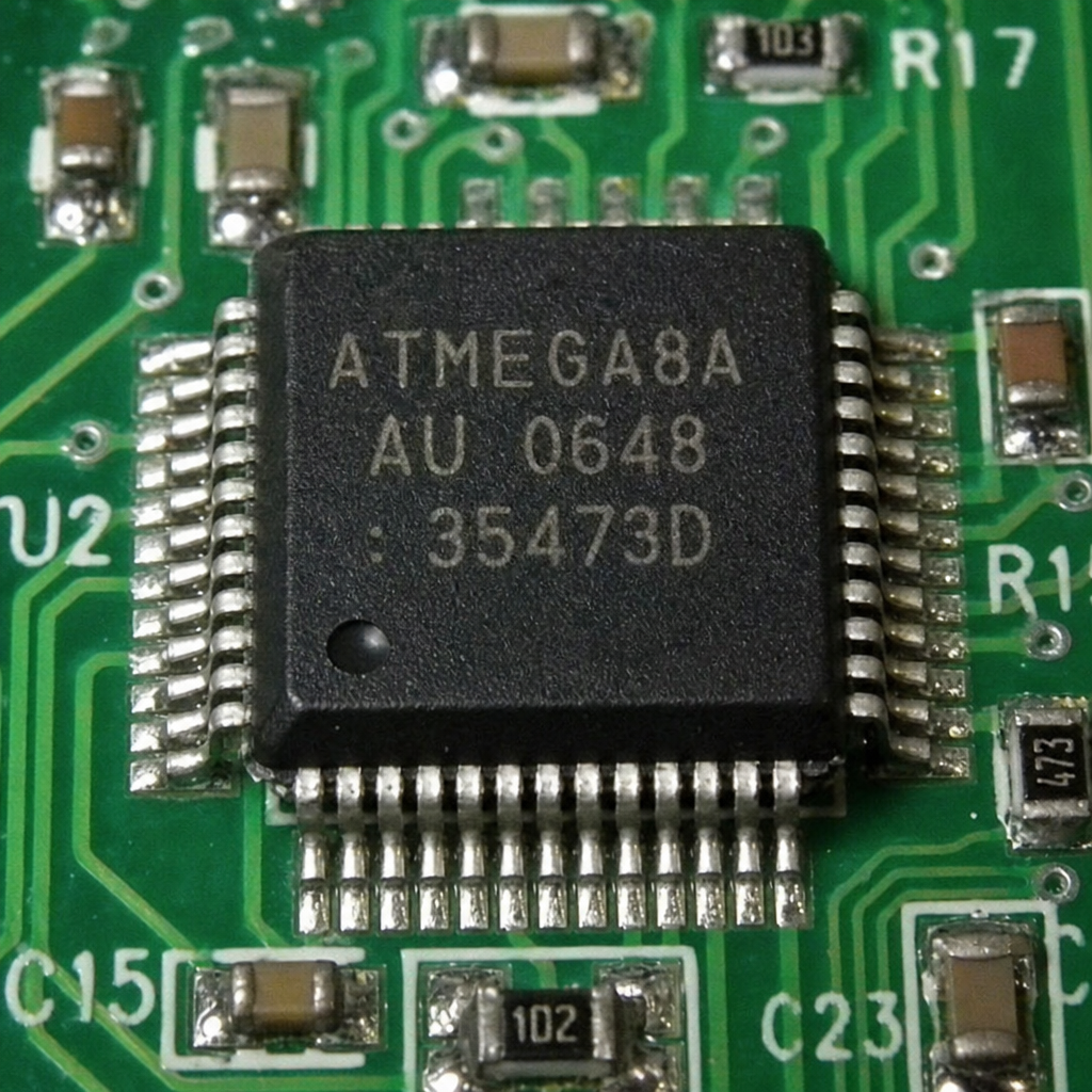
An integrated circuit, often called an IC or microchip, is a miniature electronic circuit built on a semiconductor base, usually silicon. Instead of wiring separate electronic components together one by one, an IC places components such as transistors, resistors, diodes, and sometimes capacitors into a single compact structure. That tiny structure can then be attached to a circuit board and connected to the rest of a product.
The easiest way to picture it is to imagine a city shrunk onto a fingernail-sized piece of material. There are pathways, switching points, power routes, and neighborhoods that perform different jobs. Some areas handle calculations, some store information, some control timing, and some amplify or process real-world signals.
Integrated circuits matter because they make electronics practical at scale. A circuit that once required many separate parts and a large physical layout can often be replaced by one small chip. That saves space, reduces power use, improves consistency, and makes mass production possible. It also gives designers more freedom when creating compact products.
You can find ICs almost everywhere. They appear in digital circuits that process ones and zeros, analog circuits that handle smooth real-world signals, power circuits that control energy flow, communication circuits that send and receive information, and memory circuits that store data. In short, if a device is electronic and even slightly modern, it probably contains several integrated circuits.
The basic idea behind electronic components on a chip
Traditional electronics rely on individual electronic components mounted on a board. A resistor limits current, a capacitor stores charge, a diode controls current direction, and a transistor switches or amplifies signals. These parts still matter, and many products use them alongside ICs. The breakthrough of the integrated circuit is that many of these functions can be created inside one chip.
At the heart of most ICs is the transistor. A transistor acts like a tiny controlled gate. It can turn a current on or off, or it can adjust a signal in a more gradual way. When millions or billions of transistors work together, they can perform logic, store bits, process images, run software, manage power, or translate radio signals.
Not every IC is complex. Some chips perform a simple job, such as regulating voltage or amplifying audio. Others are highly advanced and contain an entire computing system. The key point is integration: many useful circuit elements are combined into a single manufactured device.
That integration creates several practical advantages:
- Smaller size: Many functions fit into less physical space.
- Better reliability: Fewer separate connections can mean fewer potential failure points.
- Lower cost at volume: Once a design is ready, large numbers of chips can be produced efficiently.
- Lower power use: Shorter internal connections can reduce wasted energy.
- Consistent performance: Chips made from the same design tend to behave predictably within their rated limits.
This does not mean separate parts have disappeared. A real product still needs connectors, sensors, antennas, displays, power supplies, and support components. But the IC usually does much of the thinking, timing, measuring, converting, or controlling.
How does an integrated circuit work?
An integrated circuit works by moving electrical signals through carefully designed microscopic pathways and components. These signals may represent digital information, such as binary data, or analog information, such as sound, temperature, light, or radio waves. The chip’s internal design determines how those signals are switched, amplified, filtered, stored, converted, or controlled.
In digital circuits, the IC usually treats signals as two states: high and low, often understood as 1 and 0. Logic gates combine these states to make decisions. A simple logic gate can answer questions such as “are both inputs on?” or “is either input on?” When huge numbers of gates are arranged together, they form processors, memory, counters, communication controllers, and many other digital building blocks.
In analog circuits, the chip works with signals that vary continuously. An audio waveform, a sensor voltage, or a radio signal is not just on or off. It changes smoothly over time. Analog integrated circuit design focuses on preserving, shaping, amplifying, or converting these signals without adding too much noise or distortion.
Many modern chips mix both worlds. For example, a wireless device may receive an analog radio signal, convert it into digital information, process it with digital logic, and then convert a response back into an analog signal for transmission. This is why integrated circuit design often requires a balance of physics, electrical behavior, layout discipline, and product goals.
The chip does not work alone. It needs power, ground, clock signals in many cases, and connections to other parts of the device. Those connections are provided through pins, pads, balls, or leads on the chip package. The circuit board layout then carries signals between the IC and the rest of the system.
A short history of microchip development
Microchip development grew out of a simple but powerful problem: as electronic circuits became more capable, they also became larger and harder to assemble. Early electronic systems used bulky vacuum tubes and then separate transistors. These technologies worked, but they took space and required many individual connections.
The integrated circuit changed that direction. By building multiple components on one semiconductor substrate, engineers could create smaller and more reliable circuits. Over time, manufacturing improved, transistor sizes shrank, and designers learned how to place increasingly complex systems on a chip.
This steady progress made possible the personal computer, portable calculator, digital camera, smartphone, satellite navigation device, modern vehicle control system, and countless everyday products. The visible result is convenience. The hidden result is an enormous amount of design and manufacturing knowledge packed into tiny chips.
Microchip development is not only about making things smaller. It is also about making chips more efficient, easier to integrate, safer under expected conditions, and suitable for specific tasks. A chip for a smart card has different priorities than a chip for a radio, a factory controller, or a gaming console. That is why the IC world includes many specialized families instead of one universal solution.
The main types of integrated circuits
Integrated circuits can be grouped in several ways, but the most helpful starting point is to look at the kind of signals they handle and the job they perform. Most ICs fall into digital, analog, mixed-signal, power, memory, or processor-related categories. These categories often overlap, but they make the landscape easier to understand.
Digital integrated circuits
Digital ICs work with binary states. They are used when information can be represented as bits, instructions, addresses, or logical conditions. A simple digital IC may contain a few logic gates. A complex one may contain processor cores, memory controllers, encryption blocks, communication interfaces, and timing systems.
Common examples include microcontrollers, memory chips, interface chips, logic ICs, and programmable devices. These are the parts that often make a product feel “smart.” They respond to button presses, read sensors, run firmware, control displays, and communicate with other devices.
Digital circuits are popular because they are flexible. Once information is represented digitally, it can be stored, copied, checked, corrected, compressed, encrypted, and processed in many ways. That flexibility is one reason so many products now include software-controlled features.
Analog integrated circuits
Analog ICs deal with signals that vary continuously. They are useful when the real world enters the electronic system. Sound, light, pressure, acceleration, temperature, and radio energy often begin as analog signals before being converted or processed.
Examples include operational amplifiers, voltage regulators, audio amplifiers, sensor interface chips, filters, and data converters. A well-designed analog chip may quietly determine whether a product sounds clean, measures accurately, receives a signal clearly, or runs with stable power.
Analog circuits can be less obvious than digital circuits because they do not always run visible software. Still, they are essential. A digital processor cannot do much with a weak, noisy sensor signal unless analog circuitry first prepares that signal properly.
Mixed-signal integrated circuits
Mixed-signal ICs combine analog and digital sections. They are common because many real products need both. A fitness tracker, for example, may read analog sensor signals, convert them into digital data, process the results, and communicate with another device.
Data converters are classic mixed-signal components. An analog-to-digital converter turns a real-world voltage into numbers. A digital-to-analog converter turns numbers back into a continuous signal. These functions bridge the physical world and the digital world.
Mixed-signal design can be challenging because noisy digital switching may interfere with sensitive analog sections. Good internal design, careful integrated circuit packaging, and thoughtful PCB design tips all become important when these chips are placed into a finished product.
Power management integrated circuits
Power management ICs help deliver the right voltage and current to different parts of a system. They may regulate voltage, charge batteries, monitor current, switch power rails, or protect circuits from unsafe conditions.
These chips are especially important in portable products. A phone, wearable, or handheld tool may need to stretch battery life while still powering processors, sensors, displays, radios, and memory. Good power management can improve runtime, reduce heat, and make a product more dependable.
Power ICs also appear in larger equipment. They help control motors, lighting, industrial systems, automotive electronics, and power supplies. In these designs, thermal behavior and layout discipline are often just as important as the chip choice.
Memory and processor-related ICs
Memory ICs store information. Some memory keeps data only while power is present, while other memory retains information when power is removed. Processors and microcontrollers use memory constantly to run instructions, store variables, and manage data.
Processor-related ICs include microprocessors, microcontrollers, digital signal processors, and system-on-chip devices. These parts may look similar from the outside, but their internal purpose can differ significantly. Some are built for general computing, while others are optimized for control, communication, graphics, or signal processing.
How is a microprocessor different from an integrated circuit?
A microprocessor is a type of integrated circuit, but not every integrated circuit is a microprocessor. The simplest answer to “how is a microprocessor different from an integrated circuit” is that an integrated circuit is the broad category, while a microprocessor is a specific chip designed to execute instructions and perform computing tasks.
Think of “integrated circuit” as the umbrella term. Under that umbrella are many chip types: amplifiers, regulators, memory chips, radio chips, logic chips, sensor interfaces, microcontrollers, and microprocessors. A microprocessor usually acts as the central computing engine in a system. It fetches instructions, performs calculations, manages data, and coordinates other hardware.
The phrase microprocessor vs integrated circuit can be confusing because people sometimes use “chip” casually for everything. In practical terms, the distinction matters when choosing parts. If you need to amplify a tiny microphone signal, a microprocessor is probably not the right first choice. If you need to run an operating system or perform complex software-driven tasks, a microprocessor may be exactly what you need.
A microcontroller is another related term. It is also an integrated circuit, but it typically combines a processor core, memory, and input-output features in one package. Microcontrollers are common in appliances, toys, tools, sensors, and embedded products because they can control tasks without needing as many external support chips.
Here is a simple way to remember the difference:
- Integrated circuit: Any chip that integrates circuit elements into one device.
- Microprocessor: An IC focused on processing instructions and data.
- Microcontroller: An IC that includes a processor plus built-in memory and control features.
- System-on-chip: A highly integrated IC that may include processors, graphics, memory interfaces, radios, and specialized accelerators.
Once you understand that hierarchy, the terminology becomes much less intimidating.
What happens during the IC manufacturing process?
The ic manufacturing process turns a design into a physical chip through a sequence of highly controlled steps. In simple terms, engineers create a circuit pattern, transfer that pattern onto a silicon wafer, build microscopic layers, test the finished circuits, cut the wafer into individual chips, and place each chip into a protective package.
It begins with design. Engineers define what the chip should do, how fast it should work, how much power it can use, what signals it must handle, and how it will connect to the outside world. The design is then translated into detailed physical patterns. These patterns describe where transistors, wires, contacts, and other features will be formed.
Next comes wafer fabrication. A wafer is a thin round slice of semiconductor material. During fabrication, layers are added, modified, etched, and patterned to create the chip’s internal structures. Photolithography is used to transfer tiny patterns. Doping changes electrical behavior in selected regions. Metal layers create interconnections so the components can work together.
After fabrication, the wafer contains many copies of the same chip. Each one is tested to identify working devices. The wafer is then cut into individual pieces called dies. Good dies are packaged so they can be handled, mounted, protected, and connected to a circuit board.
The final packaged IC may look simple from the outside, but it represents a long chain of careful decisions. Even a basic chip depends on design tools, materials science, clean manufacturing environments, quality testing, and packaging choices.
Integrated circuit packaging makes chips usable
A bare silicon die is fragile and difficult to use directly. Integrated circuit packaging protects the die and provides a practical way to connect it to the outside world. The package is what most people recognize as the black or sometimes metallic chip body mounted on a circuit board.
Packages come in many shapes. Some have metal legs along the sides. Some have small gull-wing leads. Others use flat pads underneath or tiny solder balls arranged in a grid. The right package depends on space, heat, signal speed, manufacturing method, cost goals, and repair needs.
Packaging affects more than appearance. It influences how heat leaves the chip, how signals travel, how easy the chip is to assemble, and how much board space it takes. A high-power chip may need a package that can move heat efficiently. A high-speed chip may need a package with short, well-controlled electrical paths. A low-cost product may choose a package that is easy to assemble in volume.
For beginners, the main lesson is simple: do not choose an IC only by its function. Check the package too. A chip may be available in several package styles, and each one can affect the circuit board layout, soldering method, and overall product design.
Newest in the store


Integrated circuit design connects purpose with physics
Integrated circuit design is the process of turning an idea into a chip that can be manufactured and used. It includes defining the function, building the circuit architecture, simulating behavior, arranging the physical layout, checking the design, and preparing it for production.
A design starts with requirements. What should the chip do? What voltage will it use? How much heat can it tolerate? How many pins are needed? Does it process digital data, analog signals, radio frequencies, or power? These choices guide everything that follows.
Digital design often begins with logic descriptions. Designers define how data moves, how decisions are made, and how timing works. Software tools help convert that logic into gates and physical structures. The design is checked repeatedly to make sure it behaves as intended.
Analog integrated circuit design takes a different kind of care. Because analog signals are sensitive to noise, component matching, temperature, and physical layout, designers must think deeply about real electrical behavior. Small layout differences can affect performance. This is why analog IC design is often described as both engineering and craft.
The layout stage is where the design becomes physical. The placement of components and connections matters. Designers must manage space, signal integrity, power distribution, heat, and manufacturability. Even though the finished chip is tiny, the design process is anything but casual.
Circuit board layout turns a chip into a working product
An IC cannot help much if it is not connected properly. Circuit board layout is the step where chips, connectors, passives, sensors, power circuits, and other parts are arranged on a printed circuit board. The board routes power and signals so the full device can operate.
Good layout is especially important because real circuits are not ideal. Copper traces have resistance and inductance. Fast signals can reflect or radiate noise. Power lines can dip or ripple. Heat can build up around dense components. Sensitive analog signals can be disturbed by noisy digital switching.
This is where practical judgment matters. A schematic may show correct electrical connections, but the physical board determines how well those connections behave. A poor layout can make a good chip seem unreliable. A careful layout can help the same chip perform as expected.
Practical PCB design tips for IC-based projects
When working with integrated circuits, a few pcb design tips can prevent many common problems. These are not advanced secrets; they are habits that make designs cleaner and easier to debug.
- Read the datasheet before placing parts. Look for recommended connections, example circuits, thermal guidance, and layout notes.
- Keep power paths short and wide when needed. Power-hungry ICs need low-resistance routes that can handle current safely.
- Place decoupling capacitors close to power pins. These small capacitors help supply quick bursts of current and reduce noise.
- Separate noisy and sensitive areas. Keep high-speed digital lines or switching power sections away from delicate analog inputs.
- Respect ground connections. A messy ground layout can create unwanted voltage differences and noise paths.
- Think about heat early. Leave copper area, airflow, or thermal vias where the chip package and power level require them.
- Check pin orientation. Many board mistakes come from rotated footprints or misunderstood pin numbering.
- Leave room for testing. Test points can save hours when diagnosing a prototype.
These habits are useful for hobby projects, student work, and professional product development. The goal is not perfection on the first try. The goal is to reduce avoidable mistakes and make the design easier to understand.
Reading datasheets without getting overwhelmed
A datasheet is the main document that explains how to use an IC. It can include features, pin descriptions, recommended operating conditions, electrical limits, timing diagrams, package drawings, example circuits, and layout guidance. At first glance, a datasheet may look dense, but you do not need to understand every detail immediately.
Start with the part description. This tells you what the chip is meant to do. Then look at the pinout so you know how it connects. Next, check the absolute maximum ratings and recommended operating conditions. The absolute maximum section is not a target; it tells you limits that should not be exceeded. The recommended section is where normal design values belong.
For digital ICs, timing information may be important. For analog ICs, gain, noise, offset, bandwidth, and supply range may matter. For power ICs, current rating, thermal resistance, switching behavior, and protection features may be critical. For communication chips, interface requirements and layout recommendations deserve careful attention.
You may also see searches for something like “14n03 integrated circuit technical specifications.” When a part number looks like this, the safest approach is to find the exact manufacturer datasheet, because similar markings can refer to different devices or packages. Do not rely only on a short listing or a seller description. Check the voltage rating, current rating, pin configuration, package, thermal limits, and recommended use case before designing it into a circuit.
A good datasheet habit is to mark three groups of information:
- Must not exceed: Ratings that protect the chip from damage.
- Must satisfy: Operating conditions required for normal behavior.
- Nice to optimize: Performance details that improve efficiency, accuracy, speed, or reliability.
This keeps the document manageable and helps you focus on decisions that affect the design.
Common IC applications in everyday life
IC applications are so broad that it is easy to stop noticing them. They are inside the products people use every day, quietly handling control, communication, sensing, storage, security, and power.
In phones, integrated circuits process touch input, manage the battery, drive the display, handle wireless communication, store data, and run software. In cars, they help control engine systems, airbags, braking systems, lighting, infotainment, sensors, and driver-assistance features. In home appliances, they manage timing, motor control, temperature sensing, user interfaces, and safety functions.
In healthcare devices, ICs may process sensor readings, manage portable power, or support communication with monitoring systems. In industrial equipment, they help control machines, gather data, isolate signals, and manage automation. In consumer audio, analog and mixed-signal ICs amplify sound, filter signals, and convert between digital and analog formats.
An integrated circuit card is another familiar example. Payment cards, identification cards, transit cards, and SIM-style modules can include a small embedded IC that stores data or supports secure communication. The visible plastic card is only the carrier. The tiny chip is where the electronic function lives.
The integrated circuit radio is also a great example of how integration changes product design. Radio circuits once required many carefully tuned separate components. Today, much of the receiving, tuning, filtering, and signal processing can be handled by compact radio-frequency and mixed-signal ICs. Designers still need antennas and careful layout, but the chip can simplify much of the core radio function.
Analog and digital circuits often work together
It is tempting to divide electronics into analog and digital worlds, but most useful products blend them. A digital thermometer, for example, begins with a physical temperature change. A sensor turns that change into an electrical signal. Analog circuitry conditions the signal. A converter turns it into digital data. A processor calculates a result. A display driver shows the number.
The same pattern appears in microphones, cameras, fitness trackers, smart speakers, motor controllers, and environmental sensors. Real-world input often begins as analog. Decision-making and storage often happen digitally. Output may return to analog through speakers, motors, lights, or radio waves.
This is why designers care about both signal types. If the analog front end is noisy, the digital result may be inaccurate. If the digital section switches too aggressively near a sensitive input, it may contaminate the measurement. If the power supply is unstable, both sides can suffer.
Understanding this relationship helps beginners avoid a common mistake: assuming that adding a powerful processor will fix every problem. Sometimes the issue is not computing power. It may be sensor placement, grounding, filtering, shielding, or power quality.
Semiconductor technology is the foundation
Semiconductor technology makes integrated circuits possible. A semiconductor is a material whose electrical behavior can be controlled. Silicon is widely used because it is abundant, well understood, and compatible with many manufacturing processes.
The magic of semiconductors is that engineers can create regions that conduct in controlled ways. By adding carefully selected impurities, they change how electrons and holes move through the material. By combining these regions, they form diodes, transistors, and other structures. By connecting those structures, they build circuits.
This may sound abstract, but the practical result is simple: semiconductor technology lets us build incredibly small switches. Those switches can be arranged into logic, memory, amplifiers, regulators, sensors, and communication circuits. The smaller and more efficient the switches become, the more capability can fit into a given space.
Still, semiconductor progress is not only about shrinking. Designers also care about power efficiency, reliability, temperature tolerance, manufacturing yield, signal quality, and cost. A chip for a rugged industrial product may prioritize durability. A chip for a wearable device may prioritize battery life. A chip for high-speed computing may prioritize performance and heat management.
Choosing the right integrated circuit for a project
Selecting an IC is part technical decision, part practical judgment. The right chip is not always the most advanced one. It is the one that fits the job, the budget, the board, the supply chain, the skill level, and the expected environment.
Start with the function. Are you trying to regulate voltage, read a sensor, store data, control a motor, receive a radio signal, or run code? Once the function is clear, narrow the search by supply voltage, input and output requirements, package type, operating temperature, communication interface, and available documentation.
Then think about how easy the chip will be to use. A part with excellent performance may still be a poor choice if it requires a difficult layout, unusual programming tools, or a package that cannot be assembled with your process. For early prototypes, it is often wise to choose parts with clear datasheets, example circuits, evaluation boards, and community or manufacturer support.
A practical selection checklist can help:
- Function: Does the IC actually solve the problem you have?
- Electrical fit: Does it support your voltage, current, speed, and signal range?
- Package: Can you solder, assemble, inspect, or manufacture that package reliably?
- Thermal needs: Will it stay within safe temperature limits?
- Support components: Does it need many external parts, and do you have room for them?
- Documentation: Is the datasheet clear enough to design with confidence?
- Availability: Can you source the part consistently for your project needs?
- Testing: Can you measure and verify that it is working correctly?
This approach keeps the decision grounded. Instead of choosing a chip because it sounds impressive, you choose it because it fits the design.
Common beginner mistakes with integrated circuits
Working with ICs is rewarding, but beginners often run into the same avoidable problems. Most of these mistakes come from treating a chip as a magic box rather than a real electrical device with limits and requirements.
One common mistake is ignoring the power supply. Many ICs are sensitive to voltage range, startup behavior, ripple, and decoupling. If the supply is unstable, the chip may reset, overheat, produce noisy output, or behave unpredictably. Always check the recommended supply conditions and place support components as advised.
Another mistake is overlooking pin functions. Some pins may need pull-up resistors, configuration connections, bypass capacitors, or special startup states. Leaving a required pin floating can cause strange behavior. Connecting a pin to the wrong voltage can damage the chip.
Layout mistakes are also common. Long traces, poor grounding, missing thermal relief, and badly placed capacitors can turn a correct schematic into a troublesome board. This is especially true for high-speed digital circuits, analog circuits, radio circuits, and power switching designs.
Finally, many people skip testing strategy. A project is much easier to debug when you can access key signals, measure power rails, and isolate sections. Test points, clear labels, and staged bring-up can make the difference between a smooth prototype and a frustrating mystery.
A simple way to think about IC-based design
If you are new to electronics, integrated circuits can feel like sealed black boxes. That feeling is normal. You do not need to know every internal detail to use an IC well. You need to understand what it does, what it needs, what it outputs, and what limits you must respect.
A useful design flow looks like this:
- Define the task. Write one plain sentence describing what the circuit must do.
- Choose the right IC category. Decide whether you need analog, digital, mixed-signal, power, memory, or processing capability.
- Read the datasheet basics. Focus on purpose, pins, operating conditions, example circuits, and layout notes.
- Design the support circuit. Add the required resistors, capacitors, connectors, clocks, or protection parts.
- Plan the circuit board layout. Place parts logically and route power, ground, and signals with care.
- Build and test in stages. Verify power first, then basic function, then full performance.
- Improve the design. Use test results to adjust layout, part choices, firmware, or protection.
This process works because it treats the IC as one part of a system. The chip is important, but power, layout, packaging, external components, firmware, and testing all contribute to success.
The future of integrated circuits feels both smaller and broader
The future of integrated circuits is not just about faster computers. Chips are spreading into more types of products, and their roles are becoming more specialized. Some ICs focus on artificial intelligence tasks. Others focus on ultra-low-power sensing, secure identity, wireless communication, energy conversion, or precise measurement.
At the same time, more functions are being combined into single packages or modules. A product may use a chip that includes processing, memory, wireless communication, and sensor interfaces together. This can shorten development time and reduce board space, though it can also make design decisions more dependent on one part.
Packaging will continue to matter. As chips become more capable, getting signals and heat in and out of the package becomes a major design challenge. Board layout will also remain important, especially as products become smaller and more connected.
For everyday users, the trend means devices that are more capable and more compact. For designers, it means more powerful building blocks, but also a greater need to understand the basics. The better you understand how an integrated circuit interacts with the rest of a product, the easier it is to make smart design choices.
Final takeaway
An integrated circuit is one of the core building blocks of modern electronics. It combines many circuit elements into a small semiconductor device that can process data, amplify signals, manage power, store information, communicate wirelessly, or control a larger system. Whether you are looking at an integrated circuit card, an integrated circuit radio, a microcontroller, a memory chip, or a power regulator, the basic idea is the same: useful electronic functions are packed into a compact, manufacturable form.
The most practical way to understand ICs is to connect the big picture with real design habits. Learn the difference between analog and digital circuits. Know why a microprocessor is only one type of IC. Read datasheets carefully, respect ratings, choose packages wisely, and give circuit board layout the attention it deserves. With those basics in place, integrated circuits become much less mysterious and much more useful.