


L298N Motor Driver Guide for Arduino Beginners

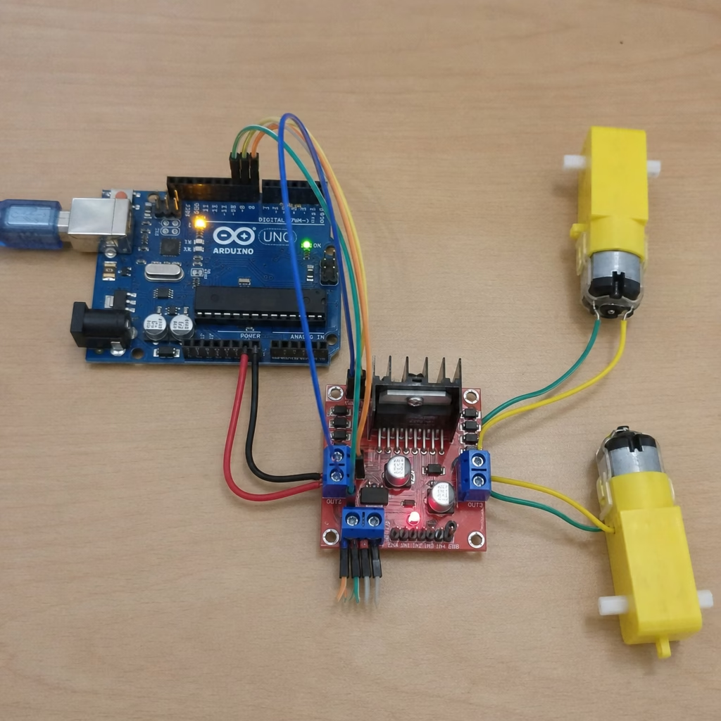
L298N Motor Driver Guide for Arduino Beginners
The L298N motor driver is a beginner-friendly module for DC motors and small stepper projects from a controller. It sits between low-power logic, such as an Arduino, and the higher-current motor load. That gives you a simple way to control speed, direction, and motion. This guide covers the l298n motor driver module in plain language, with wiring tips, pin roles, Arduino code, and common mistakes to avoid.
How does the L298N motor driver control speed and direction?
The l298n motor driver uses an H-bridge circuit for direction and PWM on the enable pins for speed. In simple terms, the H-bridge swaps which side of the motor gets positive voltage and which side goes to ground. PWM then turns motor power on and off very fast, so the motor sees an average power level you can change.
That is the core of l298n motor control. A controller cannot usually drive a motor directly because its output pins are meant for small logic signals, not motor current. The L298N acts as the power layer: the controller sends HIGH and LOW signals, and the driver handles the motor-side switching.
The module is often called an l298n dual h bridge motor driver module because it has two H-bridge channels. That means one l298n driver module can usually control two brushed DC motors separately, or one bipolar stepper motor by driving its coils in sequence.
For one DC motor, the logic is simple:
- IN1 HIGH and IN2 LOW: motor turns one way.
- IN1 LOW and IN2 HIGH: motor turns the other way.
- IN1 LOW and IN2 LOW: motor is off or coasting, depending on the board.
- IN1 HIGH and IN2 HIGH: braking may happen on many boards.
- ENA gets PWM: motor speed changes with the duty cycle.
PWM does not lower voltage in a smooth analog way. It pulses power very fast. A higher duty cycle gives more average power, so the motor spins faster. A lower duty cycle gives less average power, so the motor slows down.

The module’s main pins and what they do
A typical l298n motor driver board looks more complex than it really is. Once you separate the pins into motor outputs, logic inputs, enable pins, and power connections, the wiring becomes much easier to understand. Exact board layouts vary, so it is still smart to check the label or the l298n motor driver datasheet before you wire power.
The most important connections are:
- OUT1 and OUT2: Motor A output terminals. Connect the two wires of the first DC motor here.
- OUT3 and OUT4: Motor B output terminals. Connect the second DC motor here, or use all four outputs for a stepper motor.
- IN1 and IN2: Direction control inputs for Motor A.
- IN3 and IN4: Direction control inputs for Motor B.
- ENA: Enable pin for Motor A. Use a jumper for full speed or a PWM pin for variable speed.
- ENB: Enable pin for Motor B. Works like ENA for the second channel.
- Vs or motor supply: The positive supply for the motors, often in the 5V to 35V range depending on the module and motor.
- GND: Common ground. This must connect to both the motor power supply ground and the controller ground.
- 5V logic pin: Logic supply or regulated 5V output, depending on jumper setup and board design.
The enable pins are especially important. Many beginners leave the ENA and ENB jumpers on, then wonder why PWM speed control does not work. With the jumper on, the channel is usually enabled at full power. To use speed control, remove the jumper and connect ENA or ENB to a PWM-capable pin.
Key L298N specifications in practical terms
The l298n specifications often listed for popular boards are enough for many small robotics and learning projects, but treat them as limits, not promises. The chip is commonly used with motor supplies from 5V to 35V and is often said to support up to 2A per channel under the right conditions. In practice, heat, voltage drop, startup current, and board quality all matter.
One detail matters a lot: voltage drop. The L298N is an older bipolar-transistor-based driver, so it can lose about 2V inside under load. If you power a 6V motor from a 6V supply, the motor may get much less than 6V while running. That can make it run slower, stall sooner, or act unevenly when the robot is on the floor instead of lifted.
Also watch the onboard 5V regulator, often a 78M05-style part on many modules. Some l298n motor driver module boards include a jumper that enables the regulator when the motor supply is in a practical range, often up to about 12V. If the motor supply is higher, you may need to remove the jumper and feed a separate 5V logic supply. Because module designs vary, check the l298n motor driver datasheet and the seller notes.
A useful beginner checklist before powering the circuit:
- Confirm your motor voltage and expected current draw.
- Use an external motor supply rather than powering motors from the Arduino 5V pin.
- Connect all grounds together: Arduino ground, driver ground, and motor supply ground.
- Remove ENA or ENB jumpers if you want PWM speed control.
- Check the 5V regulator jumper before using supplies above beginner-safe ranges.
- Add a heatsink or airflow if the driver becomes hot during testing.
- Expect some voltage loss across the driver and size your supply accordingly.
A simple L298N wiring guide for Arduino projects
An arduino l298n setup is one of the most common ways to learn motor control because the logic is simple and the parts are easy to find. The Arduino sends digital signals to the input pins and PWM signals to the enable pins. The motor power supply goes to the l298n motor driver board, not to the Arduino logic pins.
For a two-motor robot, a typical l298n wiring guide might look like this in words:
- Connect the left motor to OUT1 and OUT2.
- Connect the right motor to OUT3 and OUT4.
- Connect Arduino digital pins to IN1, IN2, IN3, and IN4.
- Connect Arduino PWM pins to ENA and ENB if you want speed control.
- Connect the battery positive to the motor supply terminal.
- Connect battery negative to driver GND.
- Connect Arduino GND to the same driver GND.
- Power the Arduino through USB or an appropriate input supply.
That shared ground connection is not optional. Without a common reference, the L298N may not read the Arduino’s HIGH and LOW signals correctly. This is a common cause of motors twitching, spinning randomly, or not responding at all.

Basic Arduino logic for motor control
A short l298n tutorial does not need a big program. The key is to assign pins, set the direction pins as outputs, and use PWM on PWM-capable enable pins. The same pattern works whether you call it motor driver l298n wiring, l298 motor driver control, or a simple DC motor driver circuit.
Example logic for Motor A:
const int ENA = 9; const int IN1 = 8; const int IN2 = 7; void setup() { pinMode(ENA, OUTPUT); pinMode(IN1, OUTPUT); pinMode(IN2, OUTPUT); } void loop() { digitalWrite(IN1, HIGH); digitalWrite(IN2, LOW); analogWrite(ENA, 180); delay(2000); digitalWrite(IN1, LOW); digitalWrite(IN2, HIGH); analogWrite(ENA, 180); delay(2000); analogWrite(ENA, 0); delay(1000); }
In this example, the value passed to analogWrite controls the PWM duty cycle. On many Arduino boards, that value ranges from 0 to 255, where 0 is off and 255 is full speed. If the motor only hums at low values, raise the PWM value step by step. DC motors need enough starting torque to beat friction, especially when connected to wheels, gears, or a heavier robot chassis.Newest in the store


For Motor B, repeat the pattern with ENB, IN3, and IN4. For stepper motors, the idea changes a bit because you drive coils in a sequence rather than simply choosing forward or reverse on one motor. The l298n h bridge motor driver can handle basic stepper control, but for precise stepper projects, a dedicated stepper driver may be easier to tune.
Common L298N applications and when to choose another driver
Common l298n applications include small robots, line-following cars, simple conveyor models, motorized arms, micro mouse projects, and classroom demos. The module is popular because it is inexpensive, easy to wire, and forgiving enough for basic tests. If your goal is to learn how a dual h-bridge driver works, the L298N is a practical place to start.
It is not always the best driver for every project, though. The voltage drop and heat generation can be frustrating in battery-powered robots where efficiency matters. If your motor is close to the driver’s current limit, or if your project needs long run time, a modern MOSFET-based driver may perform better.
Consider alternatives when:
- Your driver becomes too hot to touch after short tests.
- Your robot feels weak even with a suitable battery.
- You need efficient battery use for a mobile project.
- Your stepper motor needs accurate current limiting.
- Your project requires quiet, smooth, precise motion.
Drivers such as A4988 and DRV8825 are often used for stepper motors because they provide current limiting and microstepping features. For DC motors, many newer H-bridge boards are more efficient than the L298N. Still, the l298n motor driver remains useful for learning, prototyping, and low-to-moderate power builds where simplicity matters more than maximum efficiency.
Troubleshooting the problems beginners see most
If your motor does not spin, start with power and grounding before changing the code. Make sure the motor supply is connected to the correct terminal, the ground is shared with the controller, and the enable pin is actually enabled. Then test one motor channel at a time with a simple forward command.
If the motor spins in the wrong direction, swap the two motor wires or reverse the HIGH and LOW states in code. If speed control does not work, check whether the ENA or ENB jumper is still installed. If the module overheats, reduce load, lower current demand, improve cooling, or use a driver better matched to the motor.
If the motor stalls, the issue may not be the code at all. Motors draw much more current when starting or when blocked than they do while spinning freely. A weak battery, undersized supply, loose wire, or internal voltage drop can all cause a motor that works on the bench to fail under real load.
The practical takeaway
The L298N is best understood as a bridge between logic and motion. Your Arduino or controller decides what should happen, and the l298n motor driver switches the motor power so the project can move. Once you understand the enable pins, direction inputs, shared ground, voltage drop, and power jumper, the module becomes much less mysterious.
For beginners, the l298n motor driver module is still a useful learning tool. It teaches the basics of a motor driver circuit, introduces PWM speed control, and makes H-bridge direction control easy to see in a hands-on way. Use it within its limits, wire it carefully, and you will have a solid base for more advanced motor control projects later.
Q&A
Question: Why can’t an Arduino drive a DC motor directly without an L298N?
Short answer: An Arduino pin is meant for low-power logic signals, not the higher current a motor needs. The L298N is the power layer between the controller and the motor, so the controller only sends HIGH, LOW, and PWM signals while the driver handles the motor power.
Question: Do I need to remove the ENA or ENB jumper for speed control?
Short answer: Yes, if you want variable speed with PWM. With the ENA or ENB jumper on, that channel is usually held at full power. To control speed, remove the jumper and connect ENA or ENB to a PWM-capable pin.
Question: Why is a shared ground connection so important?
Short answer: The Arduino, motor driver, and motor supply need a common ground so the L298N can read the HIGH and LOW signals correctly. Without that shared reference, motors may twitch, spin randomly, or fail to respond.
Question: Why might a motor run weakly even when battery voltage matches the rating?
Short answer: The L298N can lose around 2V inside under load because it is an older bipolar-transistor-based driver. That means a 6V motor on a 6V supply may receive less than 6V, which can cut speed, torque, and reliability under real load.
Question: When should I use a different driver?
Short answer: Use another driver if the L298N gets too hot, the robot feels weak, battery efficiency matters, or the project needs precise stepper control. Modern MOSFET-based DC motor drivers are often more efficient, while stepper drivers such as A4988 and DRV8825 offer current limiting and microstepping.