


Buck Converter Circuit: 7 Parts and How They Work

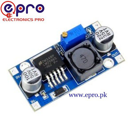
Last checked: 18 October 2026. Any prices below are dated Epro listing examples, not guaranteed current quotations. Confirm the exact model, stock and package before ordering.
A buck converter circuit reduces DC voltage by switching energy through an inductor and regulating the result. It is not simply a resistor that drops a fixed number of volts. Understanding the main functions helps you interpret a module’s specifications and avoid choosing parts from a headline current rating alone.

This is a conceptual guide, not a complete construction design. A real power stage requires component calculations, stability analysis, thermal evaluation and careful PCB layout. Work with low-voltage DC and use a documented module or reference design for practical projects.
1. The controlled switch
The switch connects the input to the energy-transfer path for part of each switching cycle. A controller changes the on-time as needed. A typical regulator integrates some functions into an IC, while other designs use external power devices. Switching frequency and device losses affect efficiency and component selection.
2. The inductor
The inductor resists rapid current change and stores energy in its magnetic field. Its current rises and falls during a cycle rather than instantly switching between zero and the full load. Inductance, saturation current, resistance and temperature rating all matter. A physically large inductor is not automatically suitable for every circuit.
3. The current-return path
When the main switch is off, inductor current still needs a path. An asynchronous buck uses a diode for this function, while a synchronous design uses another controlled switch. Diode drop, switching behavior and reverse-current considerations differ between designs. Do not exchange components merely because their package size matches.
4. The output capacitor
The output capacitor helps smooth the changing inductor current and support short load variations. Capacitance, equivalent series resistance, ripple-current rating and placement affect performance. Adding the largest available capacitor is not a universal improvement; the regulator’s control design and permitted capacitor characteristics must be respected.
5. The feedback network
The controller compares a representation of the output with a reference and adjusts switching. Many adjustable modules use a resistor network and potentiometer. Poor feedback routing or an intermittent connection can cause unstable or incorrect output. Set an adjustable module with the final device disconnected, then verify it under a suitable load.
6. The controller and protection functions
The controller determines how switching responds to the measured conditions. Depending on the IC, functions can include current limiting, thermal shutdown, startup management and enable control. Do not assume that every buck converter circuit has every protection. Check the exact regulator datasheet and the complete module implementation.Newest in the store


7. Input filtering and physical layout
The input supply also sees pulsed current. Suitable local input capacitors and careful high-current loop layout reduce electrical stress and interference. Long jumper wires cannot substitute for a properly designed switching-power PCB. Connector ratings and copper heating can limit a module even when its IC has a higher headline rating.
The ideal duty-cycle relationship
For an ideal buck operating in continuous conduction, the basic relationship is Vout = D × Vin, where D is the fraction of the cycle that the main switch is on. In that simplified model, stepping 24V down to 12V suggests a duty cycle of 0.5, while 24V to 5V suggests about 0.208.
Those examples explain the principle, not the required setting or guaranteed efficiency of a real module. Losses, minimum on-time, control mode and operating conditions change practical behavior. Texas Instruments’ buck power-stage calculation note includes more realistic design considerations and component calculations.
Power and efficiency are separate questions
A 5V load drawing 1A needs 5W at the output. The input must provide more than 5W in a real converter because some power becomes heat. Efficiency is output power divided by input power, measured under specified conditions. It is not the same as the ratio of output voltage to input voltage.
Using this knowledge to select a module
Epro’s LM2596 module listing — PKR 180 is an example of an assembled step-down board. The LM2596 manufacturer’s page describes the regulator family, not a certification of every third-party board carrying that name. For buying criteria, see the module buying guide; for adjustment, use the practical setup checklist.
Common questions
Can a buck raise voltage?
A buck-only topology steps down. Use a suitable boost or buck-boost design if the application requires raising voltage.
Why does a module become hot?
Switching, conduction, magnetic and connection losses create heat. Excessive temperature requires a load, cooling or design review—not an assumption that all heat is harmless.