


PCF8574 I/O Expander: 7 Checks Before Buying

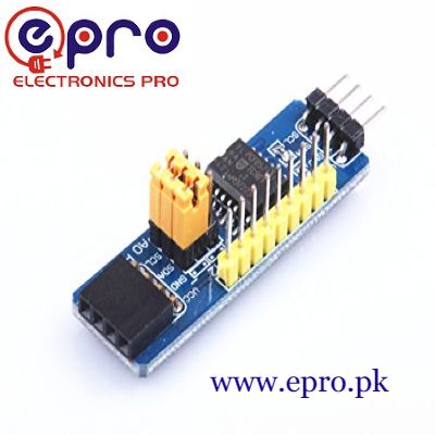
A PCF8574 adds eight remote digital port bits to an I²C bus. It can be useful for buttons and low-current indicators when controller pins are limited, but its quasi-bidirectional ports behave differently from ordinary Arduino GPIO.
Before buying, check whether you need a general-purpose expansion board or an LCD backpack. Both can contain the same chip while exposing very different connectors and board wiring. This guide concerns the general I/O expansion module.

PCF8574 price and board format
| Listed item | Price (PKR) | Project role |
|---|---|---|
| PCF8574 IO Expansion Board I2C-Bus Evaluation Development Module in Pakistan | 280 | General-purpose eight-bit I²C expansion board |
Price snapshot: Epro listings checked on 19 October 2026. Confirm the current price, availability, delivery charges and package quantity on the linked page before ordering. These are dated listing prices, not a quotation or an independent performance test.
The Epro PCF8574 expansion board is listed for adding remote digital I/O. Check the actual P0–P7 connections, address straps and supply labels. Do not assume a library written for a particular character-LCD backpack matches this board’s intended use.
1. Understand quasi-bidirectional operation
The Texas Instruments datasheet explains that each port uses a latch rather than a separate direction register. Writing a one releases the port into its weakly pulled-up state so it can also be read as an input.
Writing zero drives the port LOW. This is not equivalent to a strong push-pull HIGH output from an Arduino pin. If a button is connected to a port for input, software must leave that bit written HIGH instead of accidentally holding it LOW.
2. Match the chip suffix and address
A PCF8574 typically occupies a selectable address from 0x20 to 0x27. A PCF8574A uses a different address block, commonly 0x38 to 0x3F. Read the actual marking and straps rather than assuming a tutorial’s default address.
Two devices cannot independently respond at the same address on the same active bus. The advertised ability to expand many pins depends on unique addresses and a sound electrical bus, not merely connecting additional identical boards unchanged.
3. Keep the bus at a supported clock
The datasheet specifies a 100 kHz I²C interface for this device. A project that changes a shared bus to 400 kHz for another peripheral can create compatibility problems even though the PCF8574 worked in a simpler setup.
Document the common bus speed when combining modules. More I/O does not mean those remote pins can reproduce arbitrary fast GPIO timing, pulse capture or software-generated protocols without considering I²C transfer latency.Newest in the store


4. Review supply and pull-up voltage
The linked datasheet gives a 2.5–6 V device operating supply range. A conventional 5 V Uno is a straightforward setting for a 5 V module demonstration, but a 3.3 V controller requires an appropriate electrical arrangement.
Check where SDA and SCL are pulled up. A board powered at 5 V may pull the bus to 5 V, which is not automatically safe for a lower-voltage controller. Stacking several boards can also change the effective pull-up resistance.
5. Use outputs for suitable low-current signals
The port can sink current for a small LED when wired with an appropriate series resistor, within per-pin and total-package limits. It should not directly power a motor, relay coil, large lamp or arbitrary load.
For the first experiment, use one modest indicator rather than eight maximum-current loads. Current ratings, total dissipation and the module’s construction all matter. A digital expander is not an H-bridge or a high-power driver.
6. Preserve every input bit when writing outputs
Each transfer writes a whole port byte. Code that intends to change one LED can accidentally write zero to a button bit and stop reading it properly. Maintaining a deliberate output byte makes the intended states easier to inspect.
Reading the port returns pin states, not a substitute for remembering the intended output latch. A grounded input bit should not be copied blindly into a later output byte if it needs to remain released for input use.
7. Start with one button and one LED
The PCF8574 Arduino button-and-LED guide uses Wire directly, leaves the input bit HIGH and checks I²C transactions. It provides a clearer first test than introducing an LCD library and guessing the backpack’s internal pin mapping.
Power up with harmless loads and check the default state before attaching other electronics. A functioning input expander is not a certified safety interlock, and software or bus failures need application-specific handling in a finished design.