


PCA9555 GPIO Expander: 7 Lessons for Safe Startup and Interrupts

PCA9555 GPIO Expander: 7 Lessons for Safe Startup and Interrupts
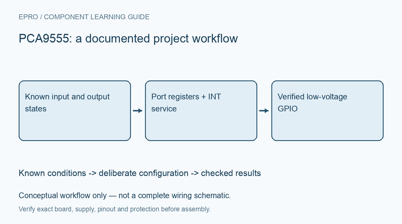
Plan PCA9555 GPIO direction, output latches and interrupt servicing with register read-back, port-aware handling and safe external load drivers. This is a documentation-based project guide, not an independent hands-on test report.
1. Treat PCA9555 as GPIO, not a power stage
NXP specifies PCA9555 as a sixteen-bit I2C and SMBus GPIO expander organized as two eight-bit ports. It adds controllable logic signals, not high-power switching capability or autonomous precision timing. Write down each pin direction, active level and safe reset behavior before assembling the circuit. Use suitable external drivers for relays or other substantial loads. The total package and port limits matter as well as an individual pin rating. Manufacturer documentation.
2. Establish the real address and levels
Inspect A0, A1 and A2 on the actual carrier and use the documented seven-bit address format. Check the supply voltage, bus pull-ups and controller input thresholds together. A statement about tolerant I/O does not mean every board signal or every connected peripheral accepts any voltage. Confirm the interrupt pull-up independently. Begin with a protected low-voltage setup and no application load connected, then verify that register reads reach the intended device. Manufacturer documentation.
3. Program latches before enabling outputs
At reset the GPIO pins default to inputs. Write the desired safe output values to the output-port registers before changing selected configuration bits to output mode. This avoids relying on reset latch values when a driver first becomes active. Test startup, processor reset and expander power cycling separately because they are not necessarily the same event. Hardware biasing should keep an external driver safe while firmware is absent. Manufacturer documentation.
4. Distinguish pin readings from latch readings
Input-port registers report pin logic, while output-port register reads report the stored output latch. These answer different questions. A latch reading back high does not prove that a loaded pin is physically high. Verify the relevant input-port reading or measure the node when diagnosing wiring. Maintain a deliberate software shadow for output changes, and serialize updates so two tasks do not overwrite each other through a stale read-modify-write sequence. Manufacturer documentation.
Newest in the store


5. Use polarity inversion only where intended
The polarity registers invert input-port data interpretation; they do not magically reverse the voltage driven by an output latch. Document active-low switches and indicators explicitly. Check both ports with known static input levels and note how the configured inversion changes software results. Keep unused inputs in defined states as appropriate for the device and board. Do not let a convenient software label obscure the actual electrical condition at a connector. Manufacturer documentation.
6. Service interrupts with port awareness
INT is an active-low open-drain change indication for input pins. It is not a FIFO containing every edge. Read the affected input port and understand that reading the other port does not necessarily clear its condition. Short pulses and repeated transitions can be missed or merge before software responds. Debounce switches in a defined software policy, and do not use this interrupt path as an assumed lossless high-speed event counter. Manufacturer documentation.
7. Verify the complete PCA9555 startup sequence
Record address straps, supply, direction masks, latch values, polarity masks and observed input states. Exercise one pin at a time before enabling a full bank, and verify interrupt recovery after a deliberately delayed service. The related MCP23017 article provides a comparison, not a compatible register map or interrupt-capture promise. A reliable design combines safe hardware defaults with measured read-back, explicit port handling and a clear distinction between requested and observed logic. Manufacturer documentation.
Related reading: MCP23017 Arduino: 7 Latch and Interrupt-Capture Checks.
Catalog note: The exact-part search did not return a matching Epro listing during preparation. Check the current catalog; this guide makes no availability, price or accessory claim.