


DAC60501 DAC: 7 Checks for a Predictable Voltage Output

DAC60501 DAC: 7 Checks for a Predictable Voltage Output
Plan a DAC60501 voltage output with the correct 12-bit coding, interface selection, reference, startup state and output-loading checks. This is a documentation-based planning guide, not a report of independent hands-on testing.
1. Identify the DAC60501 rather than its relatives
The shared manufacturer document covers DAC80501, DAC70501 and DAC60501, but their resolutions differ. DAC60501 is the 12-bit member. Do not copy a conversion formula or register payload solely because a library example names the 16-bit device. Record the complete orderable part, carrier revision and actual pin connections. A plausible response on the serial bus establishes communication, not that a requested voltage has been encoded correctly for this device. Manufacturer documentation.
2. Resolve the serial interface before wiring
The device supports SPI or I2C through its documented interface selection. Confirm how the carrier connects the selection pin and which pads expose the chosen signals. Check logic levels, pull-ups where required, supply decoupling and the common reference connection. Do not connect both interfaces by analogy with another breakout. Build a pin-assignment table from the exact package and board documentation before applying power, especially when connector labels hide configuration straps. Manufacturer documentation.
3. Document the reference and gain relationship
Choose the documented internal or external reference arrangement deliberately. Output gain and reference configuration determine the relationship between code and requested voltage, while the supply determines achievable output headroom. Record these choices together rather than leaving a library default unexplained. The existence of a nominal full-scale setting does not guarantee that a particular supply and load can support that voltage. Check the specified operating conditions before choosing endpoints for the application. Manufacturer documentation.
4. Treat startup as a separate output state
The device family includes zero-scale and midscale power-on variants. Confirm the suffix and reset behavior of the exact part instead of assuming the output remains harmless until the first serial transaction. Downstream equipment may react during host boot, reset or interface initialization. Where an unexpected analog level matters, design an appropriate independent enable or safe-state mechanism. Software configuration after startup is not a substitute for analyzing the interval before software takes control. Manufacturer documentation.
Newest in the store


5. Generate codes with explicit bounds
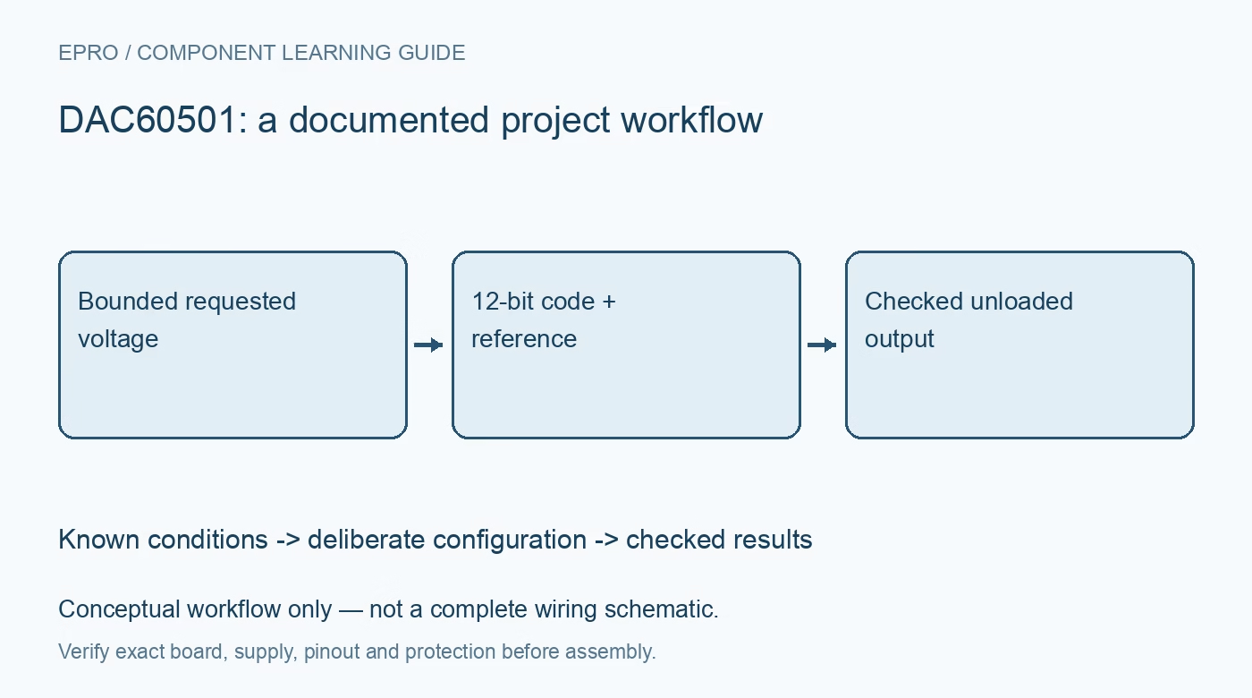
Translate the requested voltage using the selected resolution and documented transfer relationship, then validate the allowed code range before constructing the serial payload. Define what happens to negative requests, excessive requests and non-finite numeric values. Do not silently wrap an out-of-range value into an unsigned field. Keep requested voltage, selected configuration and transmitted code together in a diagnostic record so an encoding error can be distinguished from an analog output limitation. Manufacturer documentation.
6. Check the unloaded output before adding a load
Begin evaluation with suitable voltage measurement equipment and a bounded, benign output condition. Compare several documented code points without connecting the final actuator or control input. Once unloaded behavior is understood, assess the intended load against output drive, settling, capacitance and headroom limits. A voltage that changes under loading may reveal a circuit limitation rather than incorrect digital arithmetic. This guide proposes checks; it does not claim that a physical board was measured. Manufacturer documentation.
7. Keep resolution separate from system accuracy
A 12-bit code defines available steps, not the complete accuracy of the finished instrument. Reference error, offset, gain error, temperature, wiring and measurement equipment still matter. Retain the board identity, configuration, code and observed voltage with each evaluation record. The linked four-output guide offers a comparison of validation habits, not an interchangeable wiring plan. A useful DAC60501 acceptance boundary specifies both the desired voltage behavior and the conditions under which that behavior is expected. Manufacturer documentation.
Related reading: MCP4728 DAC: 7 Checks for Four Reliable Analog Outputs.
Catalog note: The exact-part search did not return a matching Epro listing during preparation. Check the current catalog; this guide makes no price, availability or included-accessory claim.