


TPL5110 Timer: 7 Steps to Reliable Power-Gated Projects

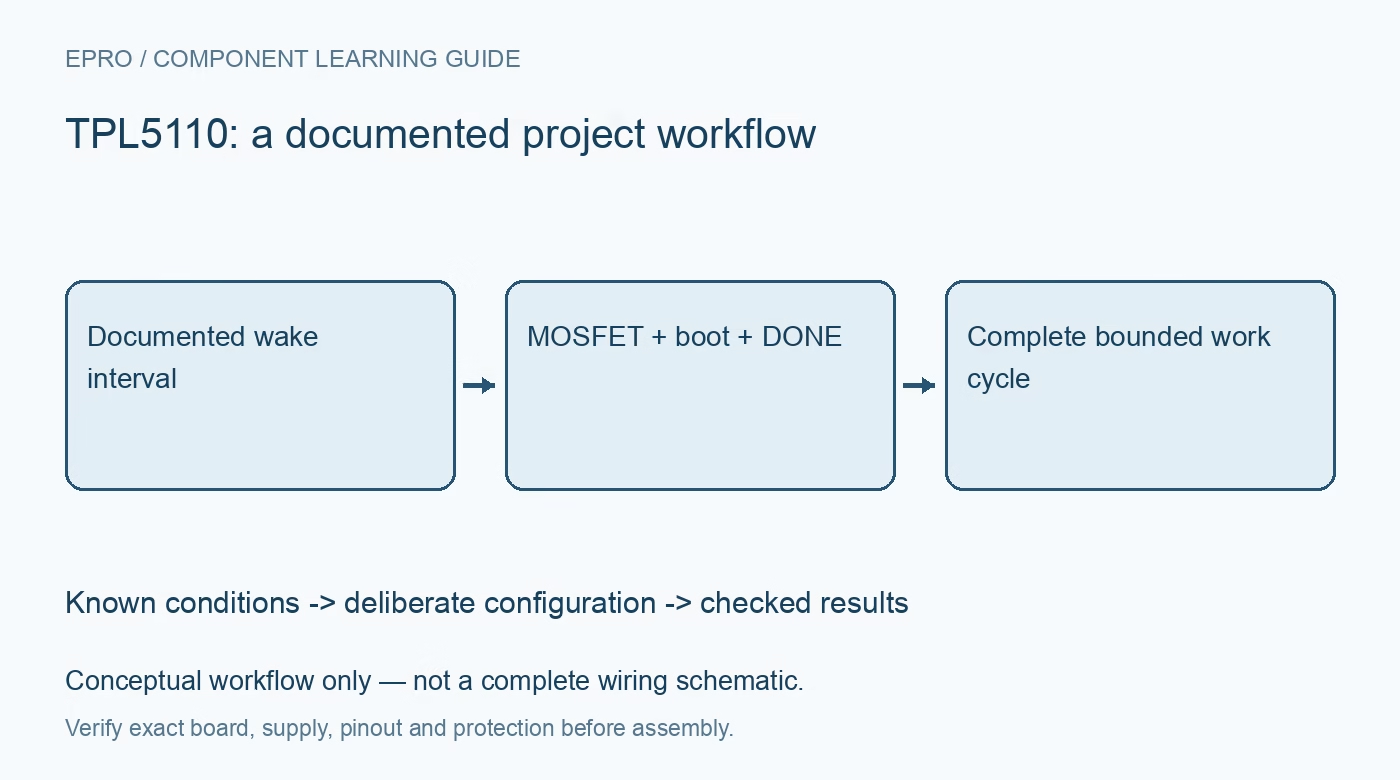
TPL5110 Timer: 7 Steps to Reliable Power-Gated Projects
Plan a TPL5110 power-gated project around its external MOSFET, timing resistor, switched-domain interfaces and deliberate DONE sequence. This is a documentation-based planning guide, not a report of independent hands-on testing.
1. Define what the TPL5110 actually switches
TPL5110 is a low-power timer intended to control power gating through an external MOSFET. It is not simply a software sleep command or a general relay module. Draw the always-powered timer domain and the switched application domain separately. Identify every component that remains powered between wake events. This distinction determines both the hardware topology and whether a claimed energy saving describes the whole project rather than only the sleeping microcontroller. Manufacturer documentation.
2. Select timing from the documented resistor method
Use the manufacturer timing tables and resistor-selection procedure for the desired interval. Keep resistor tolerance and the documented timing behavior in the project record. Do not assume an arbitrary resistor-to-seconds linear formula or change the configuration casually during operation. Review how interval selection is established during startup and how manual triggering interacts with the selected mode. The complete sequence matters more than a single nominal interval printed beside a resistor. Manufacturer documentation.
3. Size the external power path independently
Select the MOSFET and supporting circuit for the actual load voltage, startup current and dissipation. A timer control signal does not establish the allowable current of a complete carrier board. Include local decoupling and assess inrush when the application rail rises. Inspect the exact switching polarity and connections from the reference circuit. Do not substitute a visually similar transistor without checking its electrical suitability and whether it reaches the intended operating state. Manufacturer documentation.
4. Prevent power from arriving through signal pins
A switched-off processor can still receive current through a sensor, programmer, communication line or another powered device. List every signal crossing between power domains and assess it against the relevant input specifications. Use an appropriate interface arrangement where needed rather than treating a common ground as the whole solution. Back-powering can invalidate an energy budget and leave logic in an undefined state even when the main switched supply appears to be off. Manufacturer documentation.
Newest in the store


5. Make the DONE sequence an explicit contract
Firmware should finish its bounded task before presenting the documented DONE signal. Include sensor acquisition, communication completion and any persistent writes in that definition. Review the timer modes and timing diagrams because DONE behavior depends on the operating sequence; it is not an unrestricted shutdown request in every state. Initialize the host output deliberately and avoid accidental pulses during boot. Record the intended signal behavior alongside the selected interval and hardware revision. Manufacturer documentation.
6. Budget time for unsuccessful work as well
A project must handle a missing sensor or unavailable network without assuming that normal work always finishes quickly. Establish bounded retries and understand the timer response when DONE is absent or late. Assess cold boot and peripheral initialization within the available powered interval. Do not promise reliable operation based only on the nominal task duration. A repeatable design accounts for both successful work and the documented behavior when the host does not complete it. Manufacturer documentation.
7. Evaluate energy over the complete cycle
Compare energy across startup, active work and the off interval, including the timer and all always-powered parts. A low timer quiescent current alone does not establish battery life. Use a suitably protected low-voltage evaluation and retain the actual load, interval and instrumentation conditions. The linked relay-timer article is context for a different switching class, not a replacement circuit. TPL5110 validation should demonstrate orderly power-domain transitions before making any endurance or battery-life claim. Manufacturer documentation.
Related reading: AH3-3 Timer Relay Module and Timer Switch Price in Pakistan.
Catalog note: The exact-part search did not return a matching Epro listing during preparation. Check the current catalog; this guide makes no price, availability or included-accessory claim.