


INA180 Current Amplifier: 7 Checks Before ADC Readings

INA180 Current Amplifier: 7 Checks Before ADC Readings
Use an INA180 analog current-sense amplifier with deliberate gain, shunt, output-headroom and ADC-reference choices for a bounded DC circuit. This is a documentation-based planning guide, not a report of independent hands-on testing.
1. Distinguish the INA180 from a digital monitor
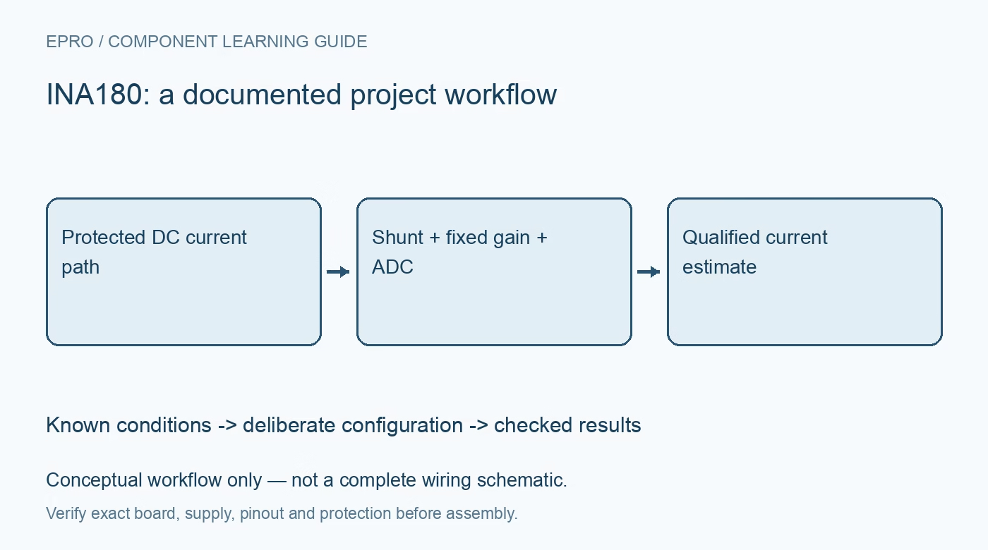
INA180 produces an analog output related to the differential voltage across a current-sense shunt. It does not contain an I2C interface that returns calibrated current registers. The host ADC and its reference are part of the measurement chain. Start with a block diagram that names the current path, shunt, amplifier and converter. A current value displayed by firmware is meaningful only when all four parts of that chain have been accounted for. Manufacturer documentation.
2. Confirm the exact fixed-gain version
The family offers different fixed-gain options, so the full part identity matters. Check the marking, orderable variant and carrier documentation before assigning a gain constant in software. INA180 should not be treated as if it had the reference-pin behavior of other related amplifiers. Establish the intended current direction and ground-referenced output behavior from its own documentation. A library gain chosen for a different part can create convincing but systematically incorrect current readings. Manufacturer documentation.
3. Choose the shunt for both signal and heat
The shunt creates a measurable voltage but also introduces burden and dissipates power. Select its resistance, tolerance, power capability and temperature behavior against the intended current range. Include normal operating conditions and credible transients without creating deliberate fault currents for demonstration. Keep the current-carrying route distinct from the voltage-sensing route where the layout permits. A larger voltage signal is not automatically an improvement if the associated burden changes the circuit being measured. Manufacturer documentation.
4. Respect common-mode and supply limits separately
Check the input common-mode requirements and amplifier supply requirements independently. Neither a supply rating nor an analog output range permits arbitrary voltage on the current-sense inputs. Review the recommended operating conditions, absolute maximum limits and any required protection for the exact circuit. This is a non-isolated measurement component, not a safe direct-mains probe. Keep introductory evaluation within a protected low-voltage DC arrangement whose current and stored energy are appropriately limited. Manufacturer documentation.
Newest in the store


5. Match the output range to the host ADC
Use the selected shunt and gain to predict the output across the desired current range. Then compare that output with both amplifier headroom and the ADC input limits. Include the ADC reference voltage and its uncertainty in the conversion equation. Do not assume an amplifier powered from one rail is automatically safe for a processor using another. Document clipping behavior explicitly so a saturated ADC code is not presented as a valid high-current measurement. Manufacturer documentation.
6. Separate offset checks from gain verification
An initial no-load observation can reveal an offset contribution, but it cannot establish the gain of the complete measurement system. Use appropriate independent reference equipment and bounded known operating points when assessing the chain. Record the raw ADC code, reference, configured gain and computed current together. Avoid automatically subtracting a startup value when the load state is unknown. That shortcut can erase a real standing current and disguise a wiring or configuration problem. Manufacturer documentation.
7. Retain conditions with every reported current
Evaluate wiring, layout, noise and sampling behavior before making accuracy claims. An output filter or averaging routine changes bandwidth and response time; it does not remove all error sources. Preserve the shunt identity, gain variant, ADC configuration and relevant temperature conditions with the results. The related INA219 guide covers a different digital architecture. A trustworthy INA180 project explains how analog voltage became current and flags samples outside the validated operating boundary instead of displaying an unexplained number. Manufacturer documentation.
Related reading: INA219 Current Sensor: 7 Buying and Calibration Checks.
Catalog note: The exact-part search did not return a matching Epro listing during preparation. Check the current catalog; this guide makes no price, availability or included-accessory claim.