


ADS122C04 ADC: 7 Checks for an Excited-Sensor Measurement

ADS122C04 ADC: 7 Checks for an Excited-Sensor Measurement
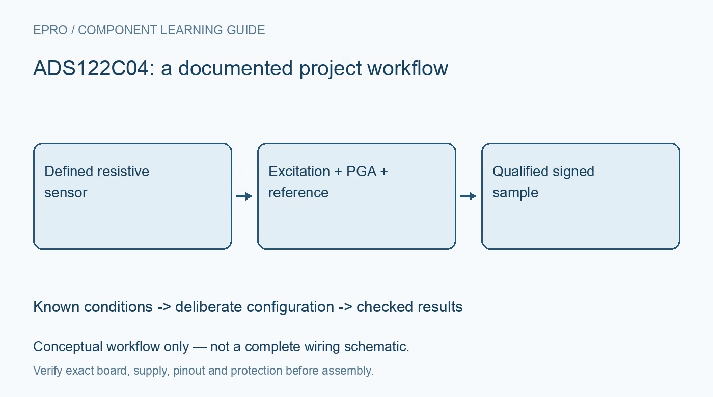
Plan ADS122C04 sensor measurements with excitation-current compliance, PGA headroom, reference selection, fresh data and optional integrity framing. This is a documentation-based planning guide, not a report of independent hands-on testing.
1. Define the ADS122C04 sensor circuit first
ADS122C04 combines a 24-bit delta-sigma converter with an input multiplexer, programmable gain and excitation-current sources. Those features support small-signal applications, but they do not define a complete resistance thermometer or bridge instrument automatically. Identify the sensor type, lead arrangement and expected electrical range before configuring the converter. Distinguish input pins from independent simultaneous conversion channels. Record the physical measurement topology rather than describing the design only as a four-channel ADC module. Manufacturer documentation.
2. Check excitation routing and compliance
If the current sources excite a resistive sensor, review their routing, programmed level and compliance requirements with the full sensor and lead resistance. Consider sensor self-heating as part of the measurement error budget. A current-source setting is not proof that the desired current reaches the sensor under every voltage condition. Keep evaluation within protected low-voltage limits, and analyze open or misconnected leads without deliberately creating hazardous faults or assuming software detects every wiring error. Manufacturer documentation.
3. Choose gain with absolute input limits
Select gain from the expected differential signal, but also verify the absolute voltages at both input pins and the PGA common-mode requirements. A small differential voltage can still accompany an invalid input condition. Review the documented bypass arrangements where relevant rather than assuming the maximum gain is always useful. Preserve gain, multiplexer selection and supply conditions together. Clipping or an out-of-range analog operating point cannot be corrected by a more elaborate host conversion formula. Manufacturer documentation.
4. Document the reference relationship
Choose the internal or external reference arrangement deliberately. In a ratiometric resistance measurement, establish how sensor excitation and reference voltage share the intended relationship instead of merely selecting an external-reference bit. Check the reference input requirements and the relevant resistor characteristics. Keep the reference choice with the conversion scale and sensor equation. A reference monitor or die-temperature feature has a different role from the external sensor and should not be presented as an automatic complete-system calibration. Manufacturer documentation.
Newest in the store


5. Account for optional counter and integrity bytes
The converter offers optional conversion-data counting and integrity arrangements that change the returned frame. Configure the host parser for the selected mode, including the documented counter and integrity coverage. Do not assume that every transaction returns only three conversion bytes. Check sign extension after extracting the actual 24-bit word. A parser that shifts an extra counter or checksum byte into the value can produce changing but meaningless readings, even when all underlying bus transactions complete successfully. Manufacturer documentation.
6. Tie acceptance to conversion completion
Use the documented conversion-control and readiness behavior for single-shot or continuous operation. Associate configuration changes with the correct subsequent measurement, and account for the external sensor and filter settling as well as converter timing. Preserve timeouts, repeated counters and failed integrity checks as quality information. Host smoothing cannot turn stale or misframed data into a valid observation. Record the actual enabled measurements and data rate when comparing results from different software revisions. Manufacturer documentation.
7. Validate the sensor model separately from the ADC
Retain excitation settings, reference arrangement, gain, lead topology, frame mode and timestamps beside raw and converted results. Evaluate the completed measurement against appropriate standards and instrumentation before claiming temperature or resistance accuracy. The related ADS1219 guide addresses a different integrated feature set and does not supply interchangeable configuration. This ADS122C04 article proposes traceable acquisition planning and claims no independent RTD calibration, guaranteed noise-free resolution or safety certification for an arbitrary connected sensor. Manufacturer documentation.
Related reading: ADS1219 ADC: 7 Checks for a Coherent 24-Bit Sensor Record.
Catalog note: The exact-part search did not return a matching Epro listing during preparation. Check the current catalog; this guide makes no price, availability or included-accessory claim.