


TMP126 SPI Sensor: 7 Checks for a Traceable Thermal Warning

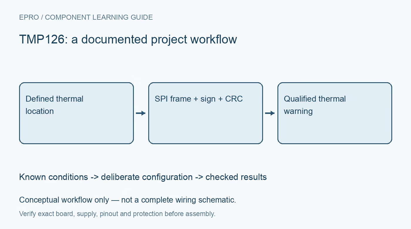
TMP126 SPI Sensor: 7 Checks for a Traceable Thermal Warning
Plan TMP126 SPI temperature monitoring with shared-data framing, signed 14-bit decoding, optional CRC and deliberate thermal-warning thresholds. This is a documentation-based planning guide, not a report of independent hands-on testing.
1. Define the TMP126 warning location
TMP126 is a digital temperature sensor with programmable limits and a temperature slew-rate warning feature. Start by deciding which physical location the sensor is intended to represent. Board temperature beside a power device is not automatically enclosure-air temperature or the temperature of the device junction. Record the mounting and heat paths before assigning alarm thresholds. A fast digital reading cannot remove thermal delay between the condition of interest and the actual sensing element. Manufacturer documentation.
2. Verify the exact part and three-wire interface
The shared documentation distinguishes TMP126 and related ordering options. Confirm the complete part and carrier before assuming identical operating or accuracy limits. Review the three-wire SPI-compatible connection and the shared-data direction requirements of the host implementation. Do not connect a separate-input, separate-output example by analogy without checking the documented signaling. Preserve supply, logic levels, clock configuration and pin assignments together. A completed host transfer is not proof that the peripheral received a correctly framed command. Manufacturer documentation.
3. Decode the aligned signed temperature field
The documented temperature data uses a 14-bit two’s complement value within the register arrangement, with the remaining low bits reserved as specified. Extract and sign-extend the field correctly before applying its scale. Do not treat the complete word as an unqualified unsigned temperature count. Check negative, zero and positive numerical examples during driver development. Retaining the raw word beside the decoded value makes it easier to distinguish arithmetic mistakes from a real thermal response. Manufacturer documentation.
4. Make CRC configuration explicit
TMP126 offers optional cyclic redundancy checking for communication integrity. If that option is enabled, implement the documented framing and checksum calculation on both read and write paths as required. Record the selected integrity mode rather than silently assuming a library default. A failed check should produce a controlled retry or invalid sample, not an ordinary temperature value. CRC supports communication checking; it does not verify thermal contact, correct sensor placement or the calibration of the completed assembly. Manufacturer documentation.
Newest in the store


5. Separate conversion cadence from thermal settling
Select the documented conversion behavior for the required update interval and power budget. Associate an accepted result with a known acquisition state and time. Repeated bus reads do not necessarily represent independent fresh thermal observations. After changing operating conditions, consider both digital conversion completion and the physical settling of the installation. A short software delay that works for one board arrangement does not establish a general response time for a different enclosure or heat source. Manufacturer documentation.
6. Configure absolute and slew warnings deliberately
Use the documented threshold and status behavior for the intended warning function. An absolute-temperature warning and a rapid-temperature-change warning answer different questions and should not be presented as interchangeable. Define host handling, acknowledgment and recovery behavior for each relevant condition. Choose thresholds from the application requirements and thermal model rather than from an arbitrary demonstration value. Independent protective mechanisms remain necessary where an overheated assembly could create damage or a hazard if software stops responding. Manufacturer documentation.
7. Retain conditions with every warning evaluation
Keep device identity, SPI configuration, integrity mode, conversion timing, placement and threshold settings with the observations. Compare against suitable reference equipment under controlled conditions before claiming system accuracy or response performance. The linked TMP119 guide concerns another sensor interface and does not provide interchangeable SPI transactions. This TMP126 workflow is documentation-based and claims no independent thermal-chamber results, universal warning thresholds or certification that a sensor alert alone protects a complete product. Manufacturer documentation.
Related reading: TMP119 Temperature Sensor: 7 Checks Beyond the Decimal Places.
Catalog note: The exact-part search did not return a matching Epro listing during preparation. Check the current catalog; this guide makes no price, availability or included-accessory claim.