


DRV8213 Motor Driver: 7 Checks Before Trusting Stall Detection

DRV8213 Motor Driver: 7 Checks Before Trusting Stall Detection
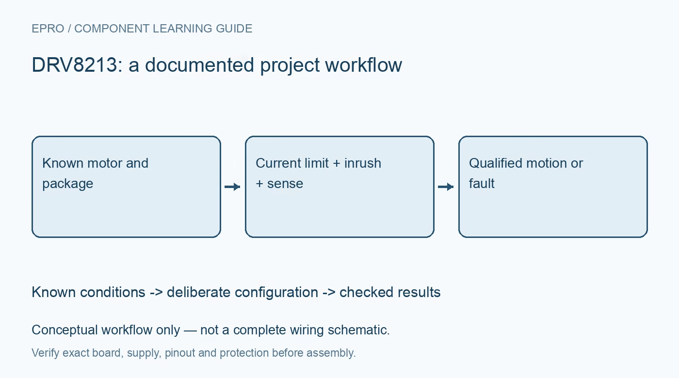
Plan DRV8213 motor control with the correct package, gain selection, current regulation, startup masking and application-specific stall handling. This is a documentation-based planning guide, not a report of independent hands-on testing.
1. Identify the DRV8213 package before features
DRV8213 integrates an H-bridge, current sensing and regulation, but the shared documentation distinguishes package-dependent capabilities. The RTE package includes the documented hardware stall-detection arrangement; another carrier should not be assumed to expose the same feature merely because its product title says DRV8213. Record the full ordering identity, package and available pins. This check comes before choosing a library example or promising that the application can detect a stalled mechanism without additional interpretation. Manufacturer documentation.
2. Match the supply and driver to the motor
Use the motor specification and actual mechanical load to assess startup demand, normal current and credible blocked-motion conditions. A peak driver-current figure is not a universal continuous rating for every carrier. Include supply capability, wiring, local capacitance and cooling. Keep early operation mechanically restrained and electrically bounded. Do not deliberately jam an unprotected mechanism to demonstrate a feature, and do not use repeated thermal or overcurrent shutdown as normal motor control. Manufacturer documentation.
3. Define control states and safe startup
Review the documented input truth table, PWM behavior and sleep sequence for the exact device. Assign a known non-driving state while the host initializes, and analyze resets or disconnected control signals. A motor that turns in both directions during a demonstration has not established controlled behavior during every transition. Keep input sequencing and the application stop policy in the design record. Where unexpected motion creates risk, provide safeguards that do not depend solely on a running firmware loop. Manufacturer documentation.
4. Configure gain and regulation deliberately
The gain-selection feature affects the documented sensing and operating arrangement. Choose it together with the VREF-based current-regulation configuration using the manufacturer relationships. Do not infer a motor limit from a potentiometer position or copy settings from a driver with a different current mirror. Preserve the selected configuration and external components. Normal current regulation and fault-level overcurrent protection serve different purposes, so a protection threshold should not be presented as the intended continuous motor operating point. Manufacturer documentation.
Newest in the store


5. Interpret current sensing in its operating context
IPROPI provides current-related information that requires appropriate external conversion and host interpretation. Check the resulting signal against ADC limits and the documented valid operating states. PWM, recirculation and startup conditions affect what an instantaneous sample means. A current rise can indicate load change, acceleration or obstruction, not uniquely a stall. Retain acquisition timing, scale and motor conditions when evaluating any decision rule that uses the current signal to classify mechanical behavior. Manufacturer documentation.
6. Qualify stall detection after the startup interval
For a package supporting the hardware feature, review threshold and inrush-related configuration against the actual motor and mechanism. Starting current must not be confused with an established stall event. Define the expected motion, permitted startup interval and response to a detection indication. A threshold that works for one load or supply may misclassify another. Evaluate through safe controlled procedures and do not treat sensorless detection as proof that every possible obstruction will be recognized. Manufacturer documentation.
7. Keep faults distinct from successful completion
Record device identity, motor, load, gain, current limit, timing configuration and diagnostics with each evaluation. A reported stall is not a universal end-stop sensor, while a cleared fault is not evidence that the underlying cause has vanished. The related DRV8411A guide discusses another bridge arrangement, not identical package features. This DRV8213 workflow proposes bounded control and detection checks and claims no independent obstruction tests, guaranteed stall classification or certification of a complete motion system. Manufacturer documentation.
Related reading: DRV8411A Motor Driver: 7 Checks for Dual-Bridge Control.
Catalog note: The exact-part search did not return a matching Epro listing during preparation. Check the current catalog; this guide makes no price, availability or included-accessory claim.