


INA240 Current Amplifier: 7 Checks Around PWM Switching

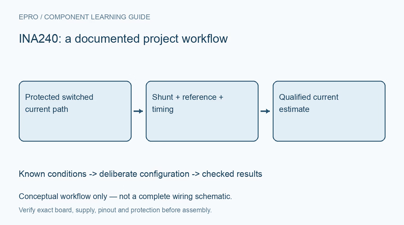
INA240 Current Amplifier: 7 Checks Around PWM Switching
Use INA240 current sensing with matched fixed gain, deliberate reference inputs, shunt routing, ADC headroom and realistic PWM-transient expectations. This is a documentation-based planning guide, not a report of independent hands-on testing.
1. Define the INA240 measurement chain
INA240 is an analog current-sense amplifier with enhanced PWM rejection. It does not return calibrated current registers over a digital bus. The complete measurement includes the shunt, amplifier, output-reference arrangement and host ADC. Draw that chain and define current direction before selecting software scaling. The PWM-rejection feature addresses common-mode switching disturbances; it should not be interpreted as a promise that every output transient, layout error or sampling problem disappears automatically. Manufacturer documentation.
2. Confirm the exact fixed-gain option
The device family offers multiple fixed gains. Record the complete variant and confirm that the carrier actually contains the expected part before choosing a firmware constant. A similar-looking package is not sufficient identification. Predict output behavior using the installed gain and the intended shunt range. Keep the configuration in the diagnostic record so a hardware substitution cannot silently produce a plausible but incorrectly scaled current value from an otherwise functioning host ADC. Manufacturer documentation.
3. Select and route the shunt deliberately
Choose resistance, tolerance, dissipation and temperature behavior against the current range and acceptable burden voltage. Keep high-current routing distinct from the sense connections where the layout permits. Analyze normal switching and credible operating transients without creating deliberate high-energy faults. A larger sense voltage is not automatically beneficial if the resulting burden or heat changes the load. Preserve the shunt specification and actual installation instead of relying only on a breakout-board current-rating headline. Manufacturer documentation.
4. Set the reference inputs for the desired output
Review REF1 and REF2 using the documented reference arrangements. They establish output referencing and support the intended unidirectional or bidirectional measurement configuration. Do not leave their role unexplained or copy the wiring of a different amplifier that lacks these inputs. Check reference-source requirements and the achievable output swing. A nominal midpoint gives a useful interpretation only when the actual reference, gain, supply and ADC range are all consistent with that choice. Manufacturer documentation.
Newest in the store


5. Check common mode and ADC limits separately
Verify the amplifier input common-mode conditions independently of its supply and output range. Then compare the predicted output with the host ADC limits and reference voltage. This is not an isolated measurement component, and a common-mode rating does not make arbitrary direct-mains probing safe. Keep introductory evaluation appropriately protected and low voltage. Define invalid or clipped readings explicitly rather than displaying a saturated code as if it were a trustworthy high-current observation. Manufacturer documentation.
6. Treat PWM timing as an acquisition variable
Enhanced rejection reduces the influence of common-mode transients, but measurement timing and settling still matter. Review the actual PWM waveform, output response, filtering and ADC sample placement using appropriate instrumentation. An average from uncontrolled sampling can obscure both switching artifacts and real current dynamics. Preserve PWM conditions and acquisition timing with evaluation data. Do not increase host averaging until a noisy trace looks smooth and then claim that the complete measurement has become accurate. Manufacturer documentation.
7. Separate offset, gain and dynamic checks
A zero-current observation can help assess offset under known conditions, but it does not establish gain or switched-load response. Evaluate those aspects independently with suitable reference equipment and bounded operating points. The related INA180 guide covers another amplifier architecture and is not a replacement reference-wiring plan. This INA240 workflow proposes traceable analog acquisition checks and claims no independent motor measurements, universal PWM immunity or finished-system accuracy based only on the presence of a current-sense amplifier. Manufacturer documentation.
Related reading: INA180 Current Amplifier: 7 Checks Before ADC Readings.
Catalog note: The exact-part search did not return a matching Epro listing during preparation. Check the current catalog; this guide makes no price, availability or included-accessory claim.