


TPS22918 Load Switch: 7 Checks for an Orderly Sensor Rail

TPS22918 Load Switch: 7 Checks for an Orderly Sensor Rail
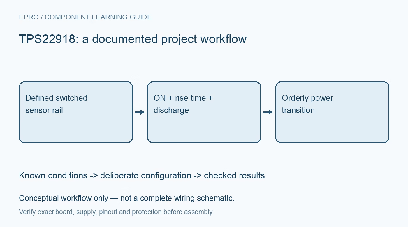
Plan TPS22918 power gating with deliberate ON behavior, CT-controlled rise time, load capacitance, output discharge and signal back-powering checks. This is a documentation-based planning guide, not a report of independent hands-on testing.
1. Define the TPS22918 switching role
TPS22918 is a single-channel load switch with configurable rise time and output-discharge behavior. It is not a voltage regulator, timer or complete battery-protection device. Identify the always-powered domain, switched rail and every load connected to that rail. Record the intended on and off conditions before selecting control components. This power-tree description determines whether switching the main supply actually powers down the intended circuit or merely leaves another path supplying it. Manufacturer documentation.
2. Check voltage, load and thermal limits
Review input voltage, load current, voltage drop and package thermal conditions for the actual carrier. A maximum current specification does not establish acceptable temperature on every board. Include source capability, wiring and load transients in the assessment. Keep the evaluation supply appropriately current limited. Do not interpret a controlled rise time as comprehensive short-circuit protection or assume a simple load switch can replace all independent source and wiring safeguards required by the application. Manufacturer documentation.
3. Establish a deliberate ON default
Review the control-input requirements and define its state while the host boots, resets or loses power. Confirm logic compatibility with the actual GPIO arrangement rather than relying on a shared ground alone. A floating or inadvertently powered control node can defeat the intended rail policy. Retain the external bias arrangement and startup sequence with the hardware revision. Where an unintended powered load matters, analyze the period before software can take control, not only the final initialized state. Manufacturer documentation.
4. Choose CT from the load and source
Use the documented CT procedure to set output rise behavior for the connected capacitance and source capability. Charging current depends on capacitance and voltage-change rate, so slower startup can reduce one source of inrush without creating a universal fixed current limit. Include effective capacitance and the load’s behavior as its voltage rises. A sensor or processor may draw additional current during startup. Evaluate the complete transition instead of choosing a timing capacitor from appearance or convenience. Manufacturer documentation.
Newest in the store


5. Analyze quick output discharge explicitly
The QOD arrangement controls how the switched output discharges under the documented conditions. Select the external connection or resistance according to the required fall behavior and energy involved. Do not assume that enabling discharge is harmless if another circuit can actively drive the output. Keep alternative power paths in the analysis. An output that falls slowly may reflect stored charge or an unintended supply, and forcing a faster discharge is not a substitute for finding the cause. Manufacturer documentation.
6. Prevent signal paths from bypassing the switch
List communication, interrupt, programming and analog connections crossing from powered domains into the switched circuit. Check whether they can source current into an unpowered device through its input structures. Choose a suitable interface or sequencing arrangement where required. A bus pull-up on an always-powered rail can matter even when the switched voltage looks near zero on a multimeter. Power-gating validation must consider the entire connected system rather than only the VIN-to-VOUT path. Manufacturer documentation.
7. Verify the full off-to-on work cycle
Record ON state, rise-time configuration, discharge path, source, capacitance and signal-domain arrangement with observations. Evaluate startup readiness and shutdown completion for the actual load using suitable instruments. The linked TPL5110 article concerns timer-driven gating, a separate control function rather than a direct TPS22918 substitute. This documentation-based workflow proposes orderly rail transitions and claims no independent inrush measurements, guaranteed battery-life savings or complete isolation merely because the main supply passes through a load switch. Manufacturer documentation.
Related reading: TPL5110 Timer: 7 Steps to Reliable Power-Gated Projects.
Catalog note: The exact-part search did not return a matching Epro listing during preparation. Check the current catalog; this guide makes no price, availability or included-accessory claim.