


TMCS1100 Hall Current Sensor: 7 Checks for a Bounded Reading

TMCS1100 Hall Current Sensor: 7 Checks for a Bounded Reading
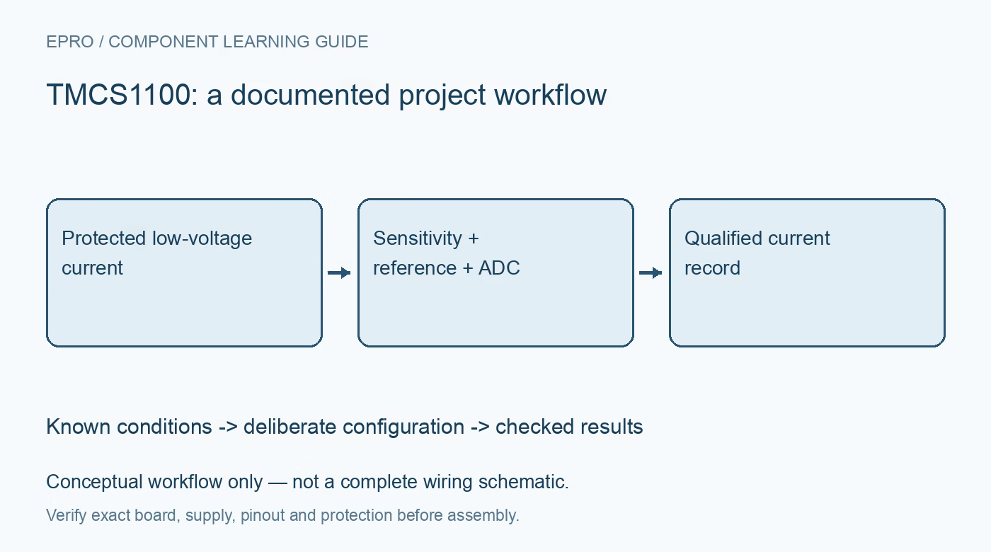
Plan TMCS1100 current measurements with the correct sensitivity, external reference, conductor limits, ADC timing and a clear component-isolation boundary. This is a documentation-based planning guide, not a report of independent hands-on testing.
1. Define the TMCS1100 sensing principle
TMCS1100 uses a Hall-effect measurement of the magnetic field generated by current through its internal conductor. It produces an analog output; it is not a digital power monitor and does not require an external shunt for the same sensing function. Draw the current path and the separate signal-side supply and ADC arrangement. Start with an appropriately protected low-voltage evaluation. The component’s galvanic-isolation features do not make arbitrary exposed wiring or a finished carrier safe for hazardous-voltage use. Manufacturer documentation.
2. Confirm the sensitivity variant
The family includes multiple fixed-sensitivity options. Record the complete part and actual carrier identity before converting an output voltage to current. A scale copied from another variant can produce plausible but systematically incorrect results. Check current direction and the documented sign convention at the conductor terminals. Preserve the selected sensitivity in the acquisition record so changing a carrier cannot silently change the physical meaning of a stored ADC code or a displayed current value. Manufacturer documentation.
3. Set the external reference deliberately
The reference input establishes the zero-current output relationship for the intended unidirectional or bidirectional measurement. Use the documented reference-source requirements and allowed range rather than assuming that any nominal midpoint is suitable. Keep reference, supply and ADC reference information together. A measured zero-current output is useful evidence only when the current state is known. Do not automatically subtract a startup value when the connected load may already be drawing real current. Manufacturer documentation.
4. Check conductor and thermal capability
The current conductor has finite resistance and dissipation, and the complete board adds its own traces, terminals and thermal constraints. Review those limits for the expected continuous and transient current. A sensitivity setting does not establish the allowable current of an arbitrary connector or carrier. Provide appropriate independent current limiting and protection. Do not demonstrate sensing by creating an uncontrolled short or assuming that a current-sensor component is also an electronic fuse or active fault interrupter. Manufacturer documentation.
Newest in the store


5. Match the output to the ADC
Predict output over the intended signed current range using the selected sensitivity and reference. Compare that prediction with sensor headroom and the host ADC input limits. Preserve clipping and invalid conditions explicitly instead of treating a saturated code as a valid high-current observation. Include the uncertainty of the ADC and its reference in any accuracy assessment. A high-resolution converter cannot recover a signal that has already clipped or been referenced incorrectly. Manufacturer documentation.
6. Relate sampling to the waveform
Select sampling, filtering and processing for the actual DC or AC current behavior. A single instantaneous value is not an RMS current, and average current alone does not describe every heating or power effect. Account for sensor bandwidth and acquisition timing when interpreting changing loads. Use appropriate reference equipment and controlled low-voltage conditions when evaluating response. Smoothing a noisy trace until it looks steady does not independently establish bandwidth, offset accuracy or correct waveform interpretation. Manufacturer documentation.
7. Keep isolation claims at the proper boundary
Retain variant, current path, reference, ADC configuration, waveform context, thermal conditions and instrumentation with results. Component isolation specifications depend on documented conditions and do not certify a complete system’s layout, insulation, clearances or enclosure. The related INA240 article covers a different shunt-based architecture, not matching wiring or scaling. This TMCS1100 workflow proposes bounded measurement checks and claims no independent isolation testing, hazardous-voltage qualification or universal accuracy for an arbitrary assembled sensor board. Manufacturer documentation.
Related reading: INA240 Current Amplifier: 7 Checks Around PWM Switching.
Catalog note: The exact-part search did not return a matching Epro listing during preparation. Check the current catalog; this guide makes no price, availability or included-accessory claim.