


TDC7200 Time Converter: 7 Checks Before Reporting Distance

TDC7200 Time Converter: 7 Checks Before Reporting Distance
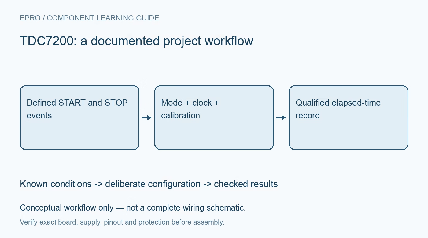
Plan TDC7200 timing with bounded START and STOP pulses, the correct measurement mode, external clock calibration, complete result parsing and physical-model limits. This is a documentation-based planning guide, not a report of independent hands-on testing.
1. Define the TDC7200 timing boundary
TDC7200 measures elapsed time between defined electrical START and STOP events. It is not a complete optical distance sensor, ultrasonic receiver or flow meter by itself. Identify what generates each edge and what physical process the interval is intended to represent. Record trigger paths and delays before choosing an application equation. A fine timing result cannot independently distinguish propagation time from delays introduced by the transmitter, receiver, comparator, wiring or digital interface. Manufacturer documentation.
2. Select the documented measurement mode
The device provides measurement modes for different elapsed-time ranges and arrangements. Choose the mode from the expected interval and documented limits rather than assuming one configuration covers every event. Include the intended number of STOP events and relevant sequence behavior in the record. A mode suitable for one laboratory pulse spacing may not support a different sensor path. Reject measurements outside the configured operating boundary instead of extrapolating a result from an incomplete or timed-out sequence. Manufacturer documentation.
3. Check START, STOP and clock interfaces
Review voltage levels, edge requirements, pulse conditions and pin connections against the exact device and carrier. Begin with compatible controlled low-voltage logic sources rather than an improvised optical or high-energy experiment. Include grounding and signal integrity in the assessment. A host SPI connection responding successfully does not prove that the timing inputs recognize the intended events. Preserve the electrical source and observation arrangement so interface problems can be separated from an actual change in elapsed time. Manufacturer documentation.
4. Treat the reference clock as measurement hardware
TDC7200 requires an external reference clock for its documented calibration and operation. Clock accuracy and behavior affect the timing result; internal self-calibration does not make an arbitrary external source ideal. Record the actual clock frequency, source and relevant characteristics with configuration data. Do not use a nominal frequency constant merely because it appears in an example project. A stable-looking register result can still have a systematic scale error when the assumed and actual clock conditions differ. Manufacturer documentation.
Newest in the store


5. Reconstruct results using the selected mode
Read the complete documented set of time, coarse-count and calibration information required for the configured measurement. Apply the manufacturer relationship with correct units and adequate numerical precision. Do not treat one convenient TIME register as a ready-made distance or universal elapsed-time value. Preserve raw results and mode identity while evaluating the implementation. Check the arithmetic independently with controlled known intervals before adding filtering, application scaling or a display that hides the underlying data. Manufacturer documentation.
6. Preserve completion and event-quality information
Use the documented status, interrupt and timeout behavior to distinguish completed measurements from missing or unsuitable events. Keep the selected STOP identity and sequence context when more than one event is involved. Repeating the last result after a missing pulse can make a failed sensor path appear normal. Averaging can reduce some variation under appropriate conditions, but it cannot remove a systematic trigger delay, repair a missing event or establish the physical meaning of an incorrectly selected pulse. Manufacturer documentation.
7. Separate time resolution from application accuracy
Retain input-event definitions, mode, clock, calibration, raw counts, validity state and reference conditions with observations. A distance or flow result needs a justified physical model and independent evaluation of the complete sensing chain. The linked VL53L4CD article concerns an integrated ranging sensor, not matching timing registers or a direct substitute. This TDC7200 workflow proposes traceable interval checks and claims no independent picosecond accuracy, complete distance calibration or finished-instrument performance from a timing-resolution headline alone. Manufacturer documentation.
Related reading: VL53L4CD Distance Sensor: 7 Steps to Valid Short-Range Results.
Catalog note: The exact-part search did not return a matching Epro listing during preparation. Check the current catalog; this guide makes no price, availability or included-accessory claim.