


TMP116 Temperature Sensor: 7 Checks for Fresh Averaged Data

TMP116 Temperature Sensor: 7 Checks for Fresh Averaged Data
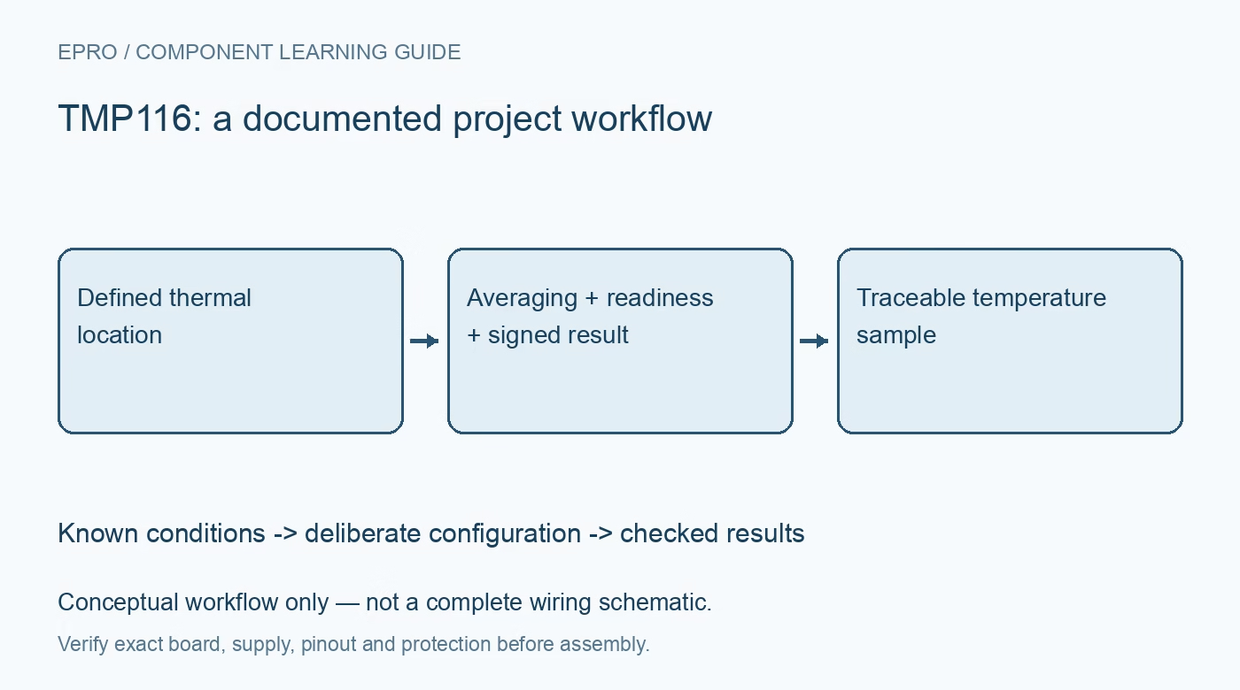
Plan TMP116 measurements with signed 16-bit decoding, deliberate averaging, data-ready handling, alert selection and careful EEPROM configuration. This is a documentation-based planning guide, not a report of independent hands-on testing.
1. Identify the TMP116 variant and thermal location
TMP116 and TMP116N share a family document but have different stated accuracy limits. Record the complete ordering identity rather than applying the most favorable family figure to every board. Define what the installation is intended to measure: a nearby component, an enclosure or another thermal location. The sensor observes its own local temperature. Connector heating, board copper and airflow can create a meaningful difference between that observation and the temperature the application actually needs. Manufacturer documentation.
2. Decode the full signed temperature word
The documented temperature result is a signed 16-bit value with a nominal step of 1/128 degree Celsius. Read the correct byte order, sign-extend the word and apply the scale once. For a numerical software check, a signed count of 3200 represents 25 degrees Celsius; this is an arithmetic example, not a measured result. Include negative values in driver tests. A display with many decimal places does not establish accuracy at the sensor or the target location. Manufacturer documentation.
3. Choose averaging and cycle time together
Review the AVG and CONV settings as a coordinated acquisition policy. Averaging changes the active measurement interval, while continuous operation can include standby time within the selected cycle. Do not assume that selecting more averages leaves latency unchanged or that reading faster creates more independent observations. Define the acceptable update interval and energy budget before choosing settings. Preserve the actual register configuration with results so readings from different timing policies are not silently compared as equivalent. Manufacturer documentation.
4. Handle data-ready reads deliberately
The documented Data_Ready flag is cleared when the configuration or temperature-result register is read. Design polling and diagnostic reads around that behavior so one task cannot accidentally consume readiness information expected by another. In one-shot operation, trigger the conversion, honor its completion conditions and distinguish timeout from a valid result. Keep an acquisition timestamp with accepted samples. A successful bus read can return a previous observation; communication success alone is not evidence of a newly completed measurement. Manufacturer documentation.
Newest in the store


5. Define the ALERT pin responsibility
Select temperature-alert, therm-style behavior or the supported data-ready indication deliberately. Review polarity, threshold and clearing behavior for that choice instead of treating all uses of the pin as interchangeable. The host needs to know whether an edge represents temperature policy or conversion completion. Preserve the chosen role through initialization and recovery. A temperature indication can support application decisions, but it does not make an otherwise unqualified circuit an independent thermal cutoff or certified protective instrument. Manufacturer documentation.
6. Treat EEPROM writes as persistent changes
The device includes EEPROM-backed configuration and general-purpose storage. Read the documented unlock, programming and busy-state procedure before changing persistent values. Avoid unnecessary writes, preserve the existing contents and do not perform conflicting writes during programming. A temporary experiment should not silently become the next power-up configuration. Record intentional changes with the board identity, and verify the loaded state after the relevant reset sequence. Do not assume another family member uses identical persistence behavior or register defaults. Manufacturer documentation.
7. Separate digital verification from thermal accuracy
Keep identity, location, averaging, cycle time, readiness policy, alert role and persistent settings with observations. Compare the complete installed assembly against suitable reference equipment under controlled conditions before making accuracy claims. The related TMP119 article addresses another device, not an interchangeable configuration file. This TMP116 guide proposes documentation-based integration checks. It reports no independent thermal-chamber measurements, calibration results or medical-device qualification, and it does not equate a fine digital step with the uncertainty of an assembled instrument. Manufacturer documentation.
Related reading: TMP119 Temperature Sensor: 7 Checks Beyond the Decimal Places.
Catalog note: The exact-part search did not return a matching Epro listing during preparation. Check the current catalog; this guide makes no price, availability or included-accessory claim.