


TMP114 Temperature Sensor: 7 Checks for Low-Voltage Thermal Data

TMP114 Temperature Sensor: 7 Checks for Low-Voltage Thermal Data
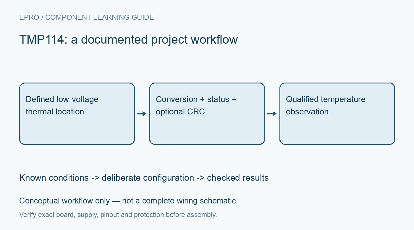
Plan TMP114 monitoring with compatible low-voltage supplies, signed decoding, deliberate averaging, read-to-clear status and optional communication CRC. This is a documentation-based planning guide, not a report of independent hands-on testing.
1. Identify the TMP114 thermal and electrical boundary
TMP114 is an ultra-thin digital temperature sensor intended for low-voltage operation. Confirm the exact variant, carrier and supply before connecting a familiar controller board. Its local temperature is not automatically the temperature of a distant component or the surrounding air. Define the intended thermal path and mounting location. Small package size can help placement, but board copper, nearby power loss and mechanical contact still influence the observation and the time needed for thermal settling. Manufacturer documentation.
2. Check supply and bus compatibility separately
The device has a narrow low-voltage supply range and documented logic thresholds. Do not assume that an ordinary 3.3-volt breakout connection is acceptable for either power or pull-ups. Review the complete interface against the actual pin limits and the carrier schematic. Count any pull-ups already installed on other boards. A successful address acknowledgment does not establish electrical compliance or prove that the interface will remain suitable through host reset and independently powered states. Manufacturer documentation.
3. Decode temperature without copying other registers
Temperature results use a signed 16-bit representation with a nominal step of 1/128 degree Celsius. Check byte order and negative-value handling explicitly. Other quantities and limit fields in this device do not necessarily use the same alignment or scale, so avoid one generic conversion routine for every register. Preserve the raw temperature word during driver evaluation. The numerical output range is not the recommended operating-temperature range, and a fine digital step does not establish installed-system accuracy. Manufacturer documentation.
4. Choose averaging and conversion timing deliberately
Review continuous, shutdown and one-shot behavior using the documented conversion and averaging controls. Averaging changes active acquisition time; it does not make a newly requested value immediately available. Define the application update interval and preserve the selected timing with accepted samples. A fast host polling loop can repeatedly receive the same result. Keep timeout and stale-data handling separate from valid observations so a missing conversion cannot quietly become a normal temperature record with a new timestamp. Manufacturer documentation.
Newest in the store


5. Preserve the read-to-clear status policy
The documented Data_Ready_Flag is cleared by reading the Alert_Status register. Coordinate application and diagnostic reads so one task does not consume information another task expects. Review high and low temperature status, retained flags and hysteresis using their specific meanings. This four-pin device provides status through its interface; do not invent a separate alert connection by borrowing another sensor’s pinout. Record whether a reported condition is current, retained from an earlier interval or unavailable after recovery. Manufacturer documentation.
6. Match CRC to the actual transaction format
Optional CRC changes the communication requirements when enabled. Use the documented polynomial, initial state and covered bytes for reads and writes instead of appending a generic checksum to ordinary transactions. Preserve configuration and reject failed integrity checks rather than displaying the decoded word anyway. CRC helps detect covered communication errors, not an unsuitable thermal location or a mistaken engineering scale. Include an intentional recovery policy for a host and sensor that no longer agree on the enabled communication format. Manufacturer documentation.
7. Keep slew and accuracy claims bounded
The supported slew-related information has its own format and mode limitations; it is not simply the temperature word divided by an arbitrary software interval. Retain variant, supply, location, timing, status and integrity state with results. The linked TMP116 article covers another sensor and clearing behavior, not an interchangeable driver. This TMP114 workflow proposes documentation-based integration checks and reports no independent thermal calibration, validated heating-rate accuracy or certified protective action from a temperature-status flag alone. Manufacturer documentation.
Related reading: TMP116 Temperature Sensor: 7 Checks for Fresh Averaged Data.
Catalog note: The exact-part search did not return a matching Epro listing during preparation. Check the current catalog; this guide makes no price, availability or included-accessory claim.