


TDC1000 Ultrasonic AFE: 7 Checks Before Accepting an Echo

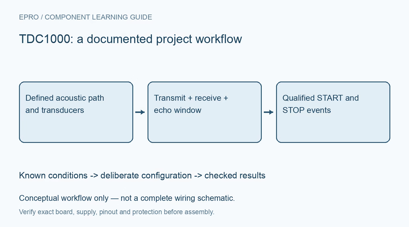
TDC1000 Ultrasonic AFE: 7 Checks Before Accepting an Echo
Plan TDC1000 sensing with matched transducers, clock-derived excitation, receiver filters, listening windows, qualified START/STOP events and a sound physical model. This is a documentation-based planning guide, not a report of independent hands-on testing.
1. Define the TDC1000 acoustic path
TDC1000 is an ultrasonic analog front end, not a complete distance instrument with an automatically calibrated length register. Define the medium, transducers, path geometry and intended reflection or transmission arrangement. Record mounting, coupling and expected echoes. A received event has physical meaning only within that arrangement. Begin with a protected low-energy setup and suitable equipment; do not improvise high-voltage excitation or assume a transmitter connection is appropriate merely because a transducer is labeled ultrasonic. Manufacturer documentation.
2. Match transducers and clock-derived excitation
Review transducer frequency and electrical requirements alongside the supported clock and transmitter configuration. The external reference and divider settings determine excitation and internal timing; they are not unrelated firmware constants. Choose the supported burst length deliberately and preserve the actual clock source. More transmit pulses do not automatically improve every measurement because ringing and near-field behavior can change. A source that responds at one convenient frequency does not establish acceptable performance across different materials, temperatures or mounting conditions. Manufacturer documentation.
3. Configure the receiver as an analog chain
Use the documented receive-channel arrangement, amplifier gain, coupling and external filtering requirements for the actual signal. A comparator threshold is not a substitute for appropriate analog bandwidth and signal quality. Too much gain can produce clipping or false events, while insufficient gain can miss useful echoes. Evaluate with suitable instruments and preserve settings. Do not adjust several controls until a plausible number appears and then describe that number as independently validated time of flight. Manufacturer documentation.
4. Define the listening and blanking window
Choose the documented short or standard time-of-flight sequencing and any applicable blanking behavior from the expected path. Account for transmitter ringing and when a valid echo can physically arrive. A window that suppresses an unwanted early event can also exclude a real short-path observation. Record that tradeoff rather than treating blanking as generic noise removal. Preserve the target range and timing assumptions so a changed transducer installation does not silently invalidate a previously suitable acquisition sequence. Manufacturer documentation.
Newest in the store


5. Treat START and STOP as timing events
The device provides START and STOP outputs for the measurement chain. Use the documented event relationship and suitable downstream timing hardware or host capability; do not treat a configuration-register read as an elapsed-time measurement. Trigger-to-START sequencing also has defined clock-related behavior. Preserve which edge begins the interval and which qualified received event ends it. A digital pulse seen on a pin can indicate the receiver recognized something without proving that it was the intended physical echo. Manufacturer documentation.
6. Distinguish missing echoes and incorrect echoes
Use documented error and sequence information to separate incomplete acquisition from an accepted event. Include timeout, repeated-echo and recovery policies in the application instead of repeating the last distance after a missing signal. Reflections from an unintended interface can still generate a convincing STOP. Evaluate known geometry and controlled changes using appropriate reference methods. Stable timing alone does not establish correct echo identity, and averaging cannot repair a systematic selection of the wrong acoustic path. Manufacturer documentation.
7. Justify the physical conversion separately
Translate elapsed time into distance, level or flow only with a model appropriate to the path and medium. Sound speed, temperature, coupling and fixed electronic delays can matter. The familiar half-round-trip relationship applies only to the corresponding reflection geometry. The related TDC7200 guide covers downstream interval conversion, not a complete acoustic receiver. This TDC1000 workflow proposes documentation-based echo checks and reports no independent range accuracy, validated flow calibration or universal performance across tanks, fluids and transducers. Manufacturer documentation.
Related reading: TDC7200 Time Converter: 7 Checks Before Reporting Distance.
Catalog note: The exact-part search did not return a matching Epro listing during preparation. Check the current catalog; this guide makes no price, availability or included-accessory claim.