


BQ25619 Charger: 7 Checks for Controlled Charge and Boost States

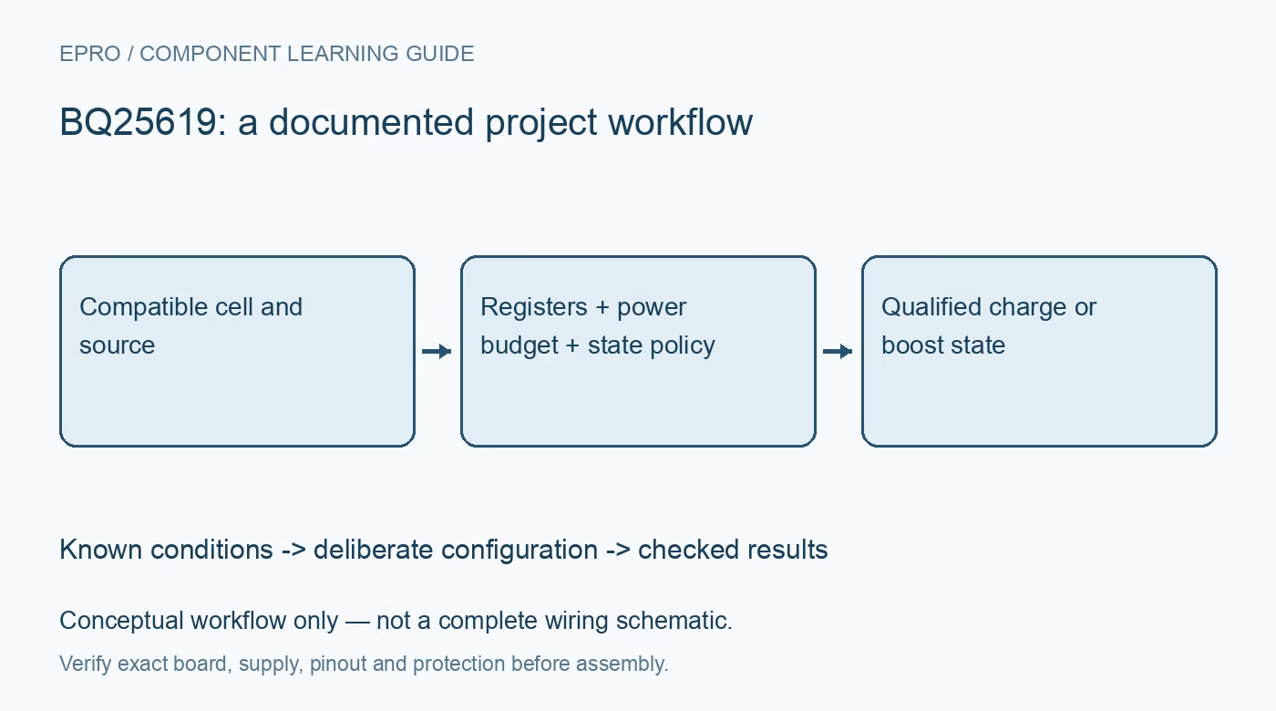
BQ25619 Charger: 7 Checks for Controlled Charge and Boost States
Plan BQ25619 operation with a compatible cell, verified I2C settings, input and system budgets, watchdog handling, fault readout and deliberate ship-mode control. This is a documentation-based planning guide, not a report of independent hands-on testing.
1. Define the BQ25619 battery system
BQ25619 integrates a one-cell switching charger, power-path functions and boost operation. Confirm the exact supported battery voltage settings and the cell manufacturer’s limits before configuring the circuit. One cell does not mean every chemistry or pack is compatible. Record cell identity, protection, temperature sensing and source requirements. Use supervised protected evaluation and suitable instruments; do not charge unknown, damaged or incorrectly identified cells merely to see whether a status bit changes. Manufacturer documentation.
2. Verify register settings rather than assumptions
Read the device identity and configuration through the documented I2C interface, then deliberately set and verify required voltage, current and operating-policy fields. Preserve reset behavior and field scaling in the driver. A copied hexadecimal byte can unintentionally modify adjacent controls as well as the intended value. Keep an explicit configuration record and use documented read-modify-write behavior where appropriate. An acknowledged write establishes communication, not suitability of the resulting charge policy for the actual battery. Manufacturer documentation.
3. Budget source, system load and charging together
Select input-current and voltage-regulation behavior from the real adapter and wiring limits. The system load and battery charging share available input power under the device’s management behavior. A charge current below its programmed target can reflect source, system or thermal constraints. Distinguish those states instead of increasing a current setting to force the expected display. Include representative load changes in the assessment and avoid converting a favorable efficiency example into an unconditional board capability. Manufacturer documentation.
4. Keep charge and boost roles distinct
Review entry, exit and regulation requirements for battery-powered boost operation separately from ordinary input-powered charging. Identify which node supplies accessories and what external protection or control components the actual board includes. A status indication does not guarantee that every connected accessory sees a safe voltage during every transition. Respect source and load limits and the documented temperature behavior. Do not assume a generic output connector automatically implements the entire charge-to-boost power-routing design. Manufacturer documentation.
Newest in the store


5. Define watchdog and reset policy
Review the charger watchdog configuration and which fields return to defaults after the relevant reset or expiration. The host must either service the selected policy appropriately or deliberately configure supported behavior. Re-read critical settings after recovery instead of assuming the previous software variables still describe the hardware. A system that continues running can nevertheless have changed charging controls. Preserve reset cause and configuration state so a communication outage cannot silently become an unexplained new battery-management policy. Manufacturer documentation.
6. Read fault and ship states deliberately
Follow the documented fault-register read sequence: a retained earlier condition and the current condition can require separate reads. Preserve useful history instead of immediately discarding every asserted flag. Review BATFET, QON and ship-mode entry and exit behavior with the complete system. An intentional low-power state can remove power needed by the host to change it later. Plan a supported recovery route and distinguish battery isolation, reset and ordinary charging status in diagnostics. Manufacturer documentation.
7. Preserve safeguards through system evaluation
Retain battery limits, temperature network, input capability, current settings, watchdog policy, boost configuration and thermal arrangement with results. Do not bypass temperature or fault protection to obtain an active charging indication. The linked BQ25185 guide concerns a different control architecture, not equivalent register or resistor settings. This BQ25619 workflow proposes documented state-management checks and reports no independent charging-cycle qualification, guaranteed shelf life or certification of a finished battery-powered product from component-level features alone. Manufacturer documentation.
Related reading: BQ25185 Charger: 7 Checks for a Compatible Power Path.
Catalog note: The exact-part search did not return a matching Epro listing during preparation. Check the current catalog; this guide makes no price, availability or included-accessory claim.