


ADS124S08 ADC: 7 Checks for a Settled Multiplexed Sensor Reading

ADS124S08 ADC: 7 Checks for a Settled Multiplexed Sensor Reading
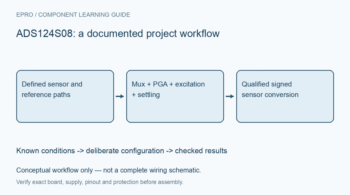
Plan ADS124S08 sensor acquisition with explicit input selection, PGA headroom, reference startup, excitation routing, filter latency and SPI integrity. This is a documentation-based planning guide, not a report of independent hands-on testing.
1. Define the ADS124S08 input arrangement
ADS124S08 provides a configurable input multiplexer feeding a precision ADC. Its multiple selectable inputs are not multiple simultaneously sampling converters. Identify the positive and negative input for each measurement and preserve that selection with the result. Review the distinction from the related six-input device in the family document. A list of channel labels in firmware does not show that the physical sensor connections, acquisition order and actual time spacing between observations are correct. Manufacturer documentation.
2. Check PGA headroom before selecting gain
Review differential range and the absolute voltage at each selected input against the analog supplies and documented PGA requirements. A small differential signal does not guarantee valid common mode. Choose gain from the complete signal envelope rather than the smallest desired display increment. Keep initial evaluation protected and low voltage; the ADC is not an isolation barrier. Include source impedance, filtering and fault behavior so out-of-range signals are explicitly rejected instead of rescaled into plausible engineering values. Manufacturer documentation.
3. Enable and select the reference deliberately
The internal reference is not automatically available in every reset configuration. Follow the documented enable and reference-selection settings, or design a compatible external or ratiometric reference path. Include reference startup and its external capacitor in the settling assessment. A correct conversion equation cannot repair a missing or unsuitable reference. Preserve which reference pair is used and how it is connected, especially where reference functions share pins with other available analog-input responsibilities on the device. Manufacturer documentation.
4. Route excitation current with the sensor circuit
The programmable current sources can support resistive-sensor excitation, but their magnitude, routing and compliance require a complete circuit assessment. Trace where each current flows and how the reference is established before enabling it. Include lead resistance and sensor self-heating in the measurement model. Do not treat the existence of two current sources as automatic cancellation of every wiring error. Preserve excitation settings alongside the selected inputs so a channel change cannot silently retain an inappropriate current path. Manufacturer documentation.
Newest in the store


5. Respect filter latency and analog settling
Choose the documented low-latency or sinc filter, data rate and conversion-start policy from the application requirement. Line-frequency rejection depends on those settings and clock conditions; it is not unconditional immunity to all interference. Account for sensor, mux, reference and filter behavior after relevant changes. Accept results only under a defined settled-data policy. A nominal samples-per-second setting does not independently specify how soon a newly selected sensor produces a valid completed observation after a configuration transition. Manufacturer documentation.
6. Parse status and CRC without shifting the result
Implement the documented SPI framing for the selected output format, including optional status and CRC bytes. Verify signed 24-bit decoding and preserve the raw transaction while evaluating the driver. If integrity checking is enabled, use its specified covered data and calculation. A valid CRC confirms covered digital consistency, not correct gain, sensor wiring or calibration. Distinguish missing-ready events, communication failures and invalid sensor status rather than repeating the last accepted result as a new conversion. Manufacturer documentation.
7. Evaluate the full sensor transfer model
Retain input selection, gain, reference, excitation, filter, timing and raw result with any derived temperature or other engineering quantity. Calibration needs known conditions and cannot compensate for every unsupported input state. The linked ADS131M02 article describes simultaneous two-channel acquisition, not equivalent multiplexed timing. This ADS124S08 workflow proposes traceable integration checks and reports no independent noise-free resolution, validated sensor accuracy or complete instrument qualification merely from a 24-bit output format and integrated excitation sources. Manufacturer documentation.
Related reading: ADS131M02 ADC: 7 Checks for Settled Two-Channel Samples.
Catalog note: The exact-part search did not return a matching Epro listing during preparation. Check the current catalog; this guide makes no price, availability or included-accessory claim.