


INA229 Power Monitor: 7 Checks for Traceable SPI Energy Records

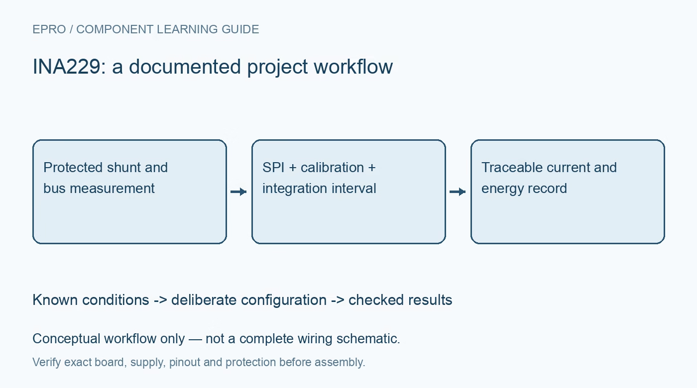
INA229 Power Monitor: 7 Checks for Traceable SPI Energy Records
Plan INA229 monitoring with correct shunt calibration, range-dependent scaling, signed register decoding, measurement timing and explicit accumulator boundaries. This is a documentation-based planning guide, not a report of independent hands-on testing.
1. Define the INA229 measurement boundary
INA229 measures shunt voltage, bus voltage and die temperature while calculating quantities including current, power, energy and charge. It uses SPI; do not assume that an otherwise similar digital power monitor’s I2C transactions apply. Draw the load path and define current direction before assigning signs. Its common-mode capability is not galvanic isolation. Keep introductory evaluation protected and low voltage, with suitable independent reference equipment and appropriate source safeguards for the actual current path. Manufacturer documentation.
2. Choose and document the physical shunt
Select shunt resistance, tolerance, power dissipation and temperature behavior from the intended current range and allowable voltage burden. Use suitable sense routing so connection losses are not accidentally included in the measured drop. The monitor cannot identify an arbitrary fitted shunt automatically. Preserve the installed value with the board revision. A small nominal resistance can reduce burden while making offset and connection effects more significant, so assess the complete uncertainty rather than only a favorable ADC specification. Manufacturer documentation.
3. Coordinate calibration and shunt-range settings
Use the manufacturer relationship for CURRENT_LSB and SHUNT_CAL with the actual resistance and expected current range. The calibration requirement changes with the documented ADCRANGE selection; do not change range while retaining an unrelated scale. Preserve the chosen numerical constants in the configuration record and check their representation. A zero or unsuitable calibration setting can make calculated quantities misleading even when raw voltage reads work. Recheck settings after reset instead of assuming host variables still describe the hardware. Manufacturer documentation.
4. Decode each register according to its format
The 20-bit measurement information and wider transferred register words require the specified alignment and signed interpretation. Energy and charge accumulators also have their own widths, units and signedness. Do not parse every SPI response with one unsigned 16-bit helper. Keep raw words and use numerical boundary cases to test the driver. A small positive load can conceal sign-extension, truncation and byte-order mistakes that become obvious only during reverse current or a longer accumulated record. Manufacturer documentation.
Newest in the store


5. Preserve conversion and averaging context
Set conversion times, enabled measurements and averaging deliberately. Calculated power relates measurements acquired through the device’s defined sequence, not an ideal simultaneous external snapshot. Rapidly changing loads can make acquisition timing important. Use documented completion information and keep accepted-sample times with results. Polling a register repeatedly does not create additional independent measurements. Define stale and unavailable states rather than attaching a new timestamp to the same observation after a failed or incomplete acquisition cycle. Manufacturer documentation.
6. Give accumulators an explicit interval
Record when energy and charge accumulation begins, when it is reset and how the application handles power loss, restart and overflow. A cumulative register without a known boundary is not a defensible daily-energy total. Review math and accumulator overflow status, and retain diagnostic context rather than silently wrapping the displayed value. Charge in coulombs is not automatically battery state of charge. Battery capacity, starting condition, efficiency and the actual monitored path remain separate model responsibilities. Manufacturer documentation.
7. Validate scale independently from logging
Retain shunt, range, calibration, SPI format, timing, interval boundaries and validity status with exported records. Compare the complete chain against suitable references at controlled conditions before claiming accuracy. The linked INA228 guide covers a related architecture with a different interface, not interchangeable bus commands. This INA229 workflow proposes documentation-based logging checks and reports no independent energy-calibration result, universal battery-gauge accuracy or safety certification merely because the monitor produces accumulated numbers. Manufacturer documentation.
Related reading: INA228 Power Monitor: 7 Steps from Shunt Choice to Energy Logs.
Catalog note: The exact-part search did not return a matching Epro listing during preparation. Check the current catalog; this guide makes no price, availability or included-accessory claim.