


INA228 Power Monitor: 7 Steps from Shunt Choice to Energy Logs

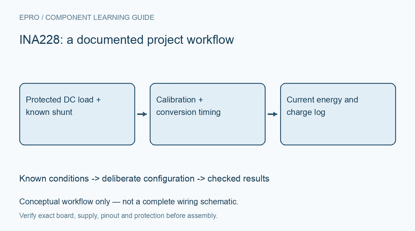
INA228 Power Monitor: 7 Steps from Shunt Choice to Energy Logs
Configure INA228 shunt calibration, signed data and accumulation state to create bounded low-voltage current, power, energy and charge records. This is a documentation-based project guide, not an independent hands-on test report.
1. Define a bounded DC experiment
INA228 combines shunt and bus-voltage measurements with calculated current, power, energy and charge outputs. Texas Instruments documents a twenty-bit measurement architecture, but resolution does not eliminate shunt, layout or timing errors. Begin with a current-limited low-voltage DC load. The chip common-mode rating is not a declaration that a breakout, breadboard or connector is safe at that voltage. This guide does not cover direct mains measurement. Manufacturer documentation.
2. Choose the shunt as a component
Determine expected current and allowable voltage drop before selecting resistance. Calculate worst-case dissipation and consider resistor tolerance, temperature coefficient and thermal rise. Check the chosen ADC shunt range, including overload margin and signal polarity. Use a suitable physical current path and Kelvin sensing where practical. A resistance printed in a product description should be verified against the fitted part and measurement arrangement rather than silently assumed in software. Manufacturer documentation.
3. Calculate and read back calibration
Select a current scaling appropriate to the documented equations, then calculate SHUNT_CAL for the actual resistance and selected range. ADCRANGE changes the applicable calibration relationship, so preserve that setting with the result. Read configuration and calibration back after writing. A sensible-looking current value can still be scaled incorrectly. Keep the chosen current LSB and derived power, energy and charge conversion factors in the project record with explicit units. Manufacturer documentation.
4. Decode width and sign carefully
Not every INA228 register has the same width or interpretation. Decode the signed current and shunt-voltage fields using their documented bit alignment, and distinguish them from unsigned quantities. Test a known zero-current condition and a modest known load before trusting a general-purpose conversion helper. Preserve raw register bytes during bring-up. Register length errors can become especially misleading when an implementation reuses assumptions from a different INA-family device. Manufacturer documentation.
Newest in the store


5. Connect timing to accumulation
Choose enabled measurements, conversion times and averaging for the application. Understand when conversions are ready and how the selected operating mode affects updates. Current, power and accumulated totals need a meaningful time history. A host display refresh is not the sensor conversion interval. Record configuration changes and periods when acquisition is disabled, then ensure graphs do not imply uninterrupted measurement through a reset, communication outage or intentional power-down. Manufacturer documentation.
6. Define reset and overflow policy
Energy and charge registers are accumulated state, not permanent lifetime counters. Follow the documented reset and diagnostic behavior, and track overflow conditions rather than assuming unlimited storage. Save a session identifier and explicit starting point with each exported total. If the controller restarts while the sensor remains powered, reconcile its existing accumulation before labeling the next value as a new session. Do not join totals from different calibration settings without accounting for their meaning. Manufacturer documentation.
7. Validate an INA228 session end to end
Compare a stable modest load with suitable reference measurements, accounting for shunt heating and instrument uncertainty. Check current polarity, bus voltage, calculated power and elapsed accumulation together. Retain raw values, scale factors, validity flags and reset events. The related INA226 guide explains external-shunt planning but is not a register-compatible implementation. A defensible energy log makes configuration and time boundaries visible rather than presenting one precise-looking total without its measurement conditions. Manufacturer documentation.
Related reading: INA226 Datasheet: Shunt Choice, Bus Voltage and Calibration.
Catalog note: The exact-part search did not return a matching Epro listing during preparation. Check the current catalog; this guide makes no availability, price or accessory claim.