


TPS55288 Buck-Boost: 7 Checks Before Enabling a Programmed Rail

TPS55288 Buck-Boost: 7 Checks Before Enabling a Programmed Rail
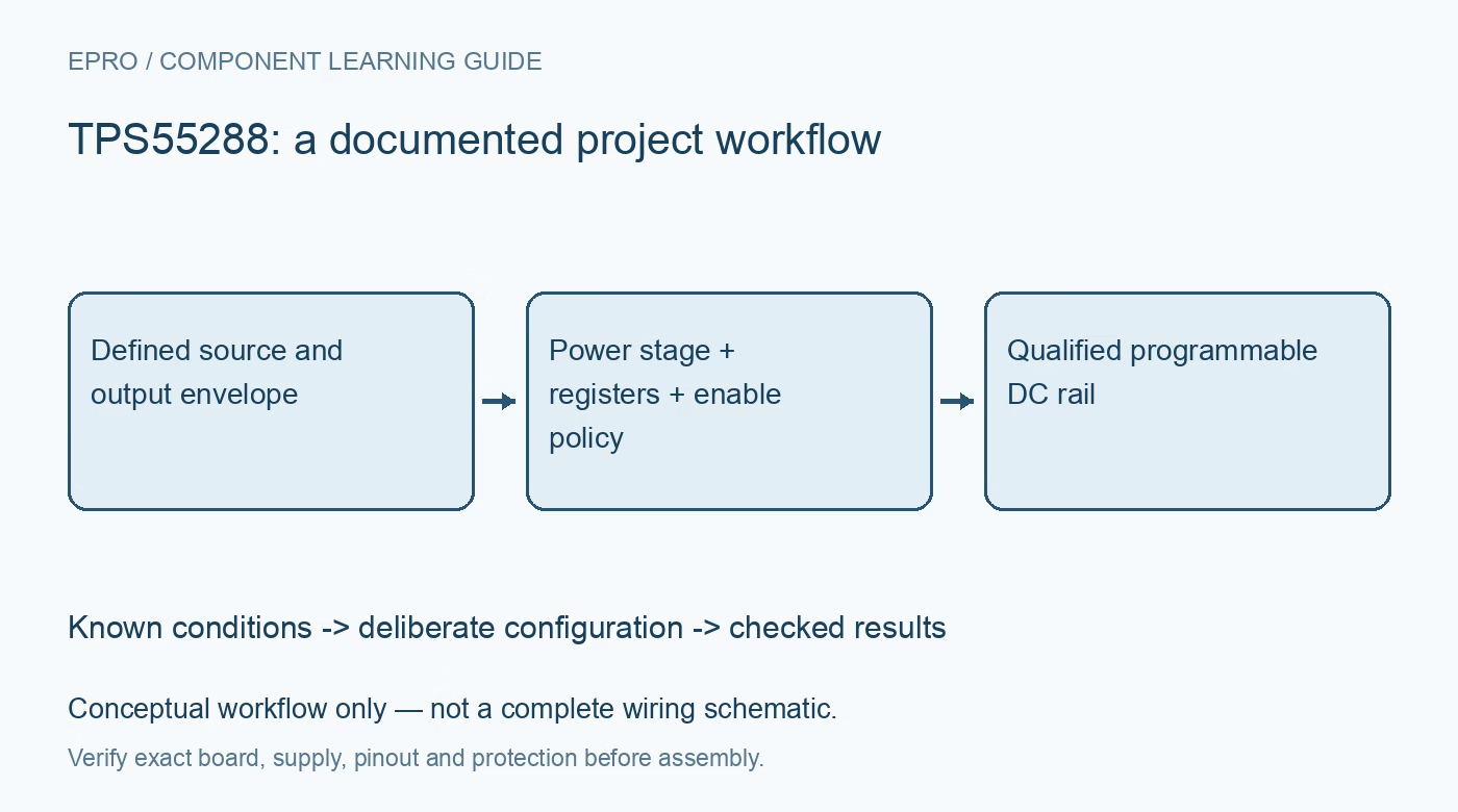
Plan TPS55288 rails with the complete external power stage, verified I2C settings, output-enable sequencing, distinct current limits and bounded source demand. This is a documentation-based planning guide, not a report of independent hands-on testing.
1. Identify the TPS55288 power-stage boundary
TPS55288 supports programmable buck-boost regulation but is not a complete power supply by itself. The documented architecture integrates the boost-side power switches and requires the appropriate external buck-side devices and supporting components. Inspect the actual carrier rather than assuming every switch and protective function is inside the IC. Define source, output voltage and load conditions first. A headline current or power figure is not a universal continuous capability of an arbitrary small board. Manufacturer documentation.
2. Budget input power across the voltage range
Evaluate source voltage, source impedance, wiring and expected load energy at the weakest intended condition. Output current and inductor or switch current describe different parts of the converter. Boosting increases input-current demand for a given delivered power. Do not infer unrestricted output current from the integrated-switch rating. Keep initial evaluation protected and low voltage, using a suitably limited source and instruments rather than beginning with an unqualified high-power load or relying on repeated protective shutdown. Manufacturer documentation.
3. Configure voltage before setting output enable
The documented startup sequence allows the host to configure registers before setting the OE output-enable bit. Use that distinction deliberately and verify the programmed target against downstream voltage limits. Review default values and the effect of hardware enable or reset. A responding I2C interface does not prove that the rail is enabled, settled or set correctly. Preserve a clear state sequence so host startup cannot unexpectedly apply a previous demonstration voltage to a different connected load. Manufacturer documentation.
4. Keep voltage scaling and feedback choices explicit
Use the documented reference and feedback arrangements for the actual board. Internal and external feedback responsibilities must match the register policy and resistor network. Predict the target voltage before enabling the load, then verify it with suitable independent equipment. A fine programming step does not establish absolute accuracy or eliminate output overshoot. Preserve voltage-change timing and the acceptable rail transition with the application so tasks that need a settled supply do not run during an uncontrolled adjustment. Manufacturer documentation.
Newest in the store


5. Distinguish the current-limit mechanisms
Review output-current sensing and limit settings separately from average and peak inductor-current protection. Confirm the relevant resistor network and how status is reported. A programmed output limit is not automatically a precise laboratory current source for every dynamic load. The source, thermal design and converter operating region still constrain available performance. Document the intended overload policy and recovery behavior instead of diagnosing every reduced rail voltage as an I2C fault or increasing limits without a complete circuit assessment. Manufacturer documentation.
6. Treat switching layout and thermal design seriously
Select external switches, inductor, capacitors and compensation using the manufacturer guidance. Follow high-current loop, gate-drive and sensing layout requirements. Switching frequency, synchronization, light-load policy and spread-spectrum choices have separate tradeoffs. A long-jumper assembly is not equivalent to the recommended compact implementation for ripple, efficiency or transient evaluation. Keep board cooling and component ratings in the operating envelope rather than presenting one favorable efficiency example as the performance of every module under every source condition. Manufacturer documentation.
7. Separate a programmable rail from USB negotiation
The converter can support a programmable supply used within a USB power-delivery system, but voltage programming alone does not implement the complete port protocol and protection design. Retain power-stage identity, source, register state, enable policy and observation conditions with results. The linked TPS63070 guide covers a different converter architecture. This TPS55288 workflow proposes documentation-based rail checks and reports no independent efficiency curve, USB compliance qualification or validated high-power operating envelope for a finished product. Manufacturer documentation.
Related reading: TPS63070 Buck-Boost: 7 Checks Across the Input-Output Boundary.
Catalog note: The exact-part search did not return a matching Epro listing during preparation. Check the current catalog; this guide makes no price, availability or included-accessory claim.