


TPS3840 Supervisor: 7 Checks for a Deliberate Reset Release

TPS3840 Supervisor: 7 Checks for a Deliberate Reset Release
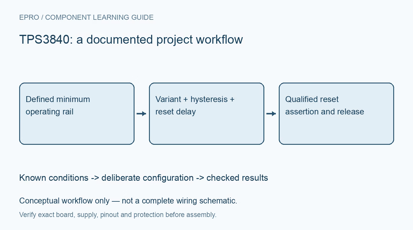
Plan TPS3840 supervision with the correct threshold and output variant, hysteresis, capacitor-programmed release delay, manual-reset behavior and startup limits. This is a documentation-based planning guide, not a report of independent hands-on testing.
1. Define the TPS3840 reset objective
TPS3840 supervises voltage and provides a reset-related output. Start with the downstream circuit’s permitted supply behavior and reset requirements rather than choosing a threshold from the nominal rail alone. Define what should happen during startup, brownout and power removal. The device does not regulate the rail, interrupt every fault current or supervise firmware progress as a watchdog would. A meaningful reset policy depends on the complete connection between the supervisor, host and power system. Manufacturer documentation.
2. Confirm threshold and output ordering options
The family includes fixed threshold options and different output topologies and polarities. Confirm the complete part code before wiring a reset input. An open-drain active-low output and a push-pull active-high output are not interchangeable merely because the base name matches. Preserve the ordering identity and threshold tolerance in the board record. A carrier description that omits these distinctions is not enough evidence to assume the host receives the intended asserted and released logic states. Manufacturer documentation.
3. Review the monitored supply and pin limits
Understand the documented VDD sensing and supply arrangement for the actual application. Direct connection and a divider-based higher-voltage design have different accuracy, current and fault considerations. Use the manufacturer approach rather than extending a pin beyond its limits because a related application drawing mentions a higher system voltage. Keep introductory evaluation protected and low voltage. The supervisor is not an isolation device, and its input range does not establish the safety of an entire high-energy installation. Manufacturer documentation.
4. Include hysteresis and threshold tolerance
A falling threshold and a rising release boundary are different conditions. Review the documented hysteresis and minimum or maximum threshold values against the load’s needs. A nominal number is not an exact switching point under every condition. Slow or noisy supply transitions can expose an unsuitable reset policy even when a steady bench voltage looks correct. Preserve the actual voltage conditions when evaluating a transition rather than reporting one convenient observed point as the guaranteed behavior of every device. Manufacturer documentation.
Newest in the store


5. Program release delay for the real startup
Use the documented CT capacitor arrangement and include component tolerance and device timing limits. Reset release delay is not the same as the detection delay for a falling supply. Choose it from rail settling, clock startup and host requirements rather than a familiar demonstration value. A reset line that releases after a nominal interval does not establish that every peripheral is ready. Evaluate the complete startup sequence using compatible instrumentation and a representative downstream load. Manufacturer documentation.
6. Check manual reset and output wiring
Review manual-reset input levels, internal bias and timing, especially when another device drives MR from a different voltage domain. Follow the applicable output pull-up and load requirements for the selected variant. Do not tie push-pull outputs together as if they were open drain. Define unpowered and very-low-supply behavior explicitly instead of assuming a valid digital indication down to zero volts. Preserve how a user action, external control or disconnected wire affects the reset policy. Manufacturer documentation.
7. Evaluate recovery beyond the supervisor pin
Retain ordering option, threshold, CT network, manual-reset arrangement, host connection and observation conditions with results. Check that a controlled brownout produces appropriate host recovery rather than an unexplained repetitive reset loop. The linked TPS3702 guide covers window detection, not matching reset-output options. This TPS3840 workflow proposes documentation-based reset checks and reports no independent brownout qualification, guaranteed recovery from every firmware fault or safety certification merely because a supervisor can assert a reset signal. Manufacturer documentation.
Related reading: TPS3702 Voltage Detector: 7 Checks for a Defined Rail Window.
Catalog note: The exact-part search did not return a matching Epro listing during preparation. Check the current catalog; this guide makes no price, availability or included-accessory claim.