


TCA9617B I2C Repeater: 7 Checks for Compatible Buffered Lows

TCA9617B I2C Repeater: 7 Checks for Compatible Buffered Lows
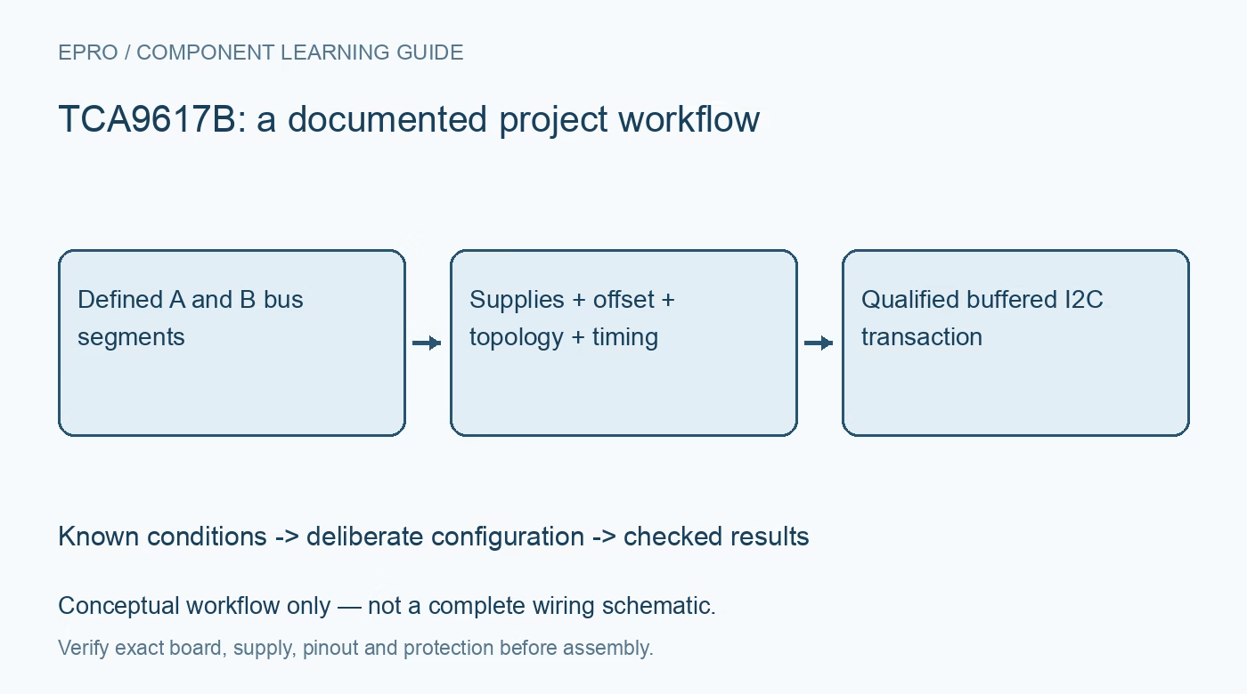
Plan TCA9617B buses with correct supply ordering, side-specific low thresholds, compatible buffer topology, segment pull-ups and realistic timing margins. This is a documentation-based planning guide, not a report of independent hands-on testing.
1. Define the TCA9617B bus segmentation
TCA9617B buffers and translates the SDA and SCL paths between two I2C bus segments. It is not a passive pass switch, a galvanic isolator or a solution to duplicate peripheral addresses. Draw both segments, their supplies, pull-ups and connected devices before selecting a topology. Preserve which endpoint is on side A and which is on side B. The device’s side-specific electrical behavior matters more than a generic two-voltage module label. Manufacturer documentation.
2. Check both supply ranges and their relationship
Review the documented VCCA and VCCB operating limits and the required relationship between them. Do not assume the two sides are symmetric because communication is bidirectional. Check endpoint logic compatibility and the actual carrier connections. A successful address scan under one powered condition does not establish correct startup, disabled or independently unpowered behavior. Keep evaluation within the specified low-voltage boundaries and account for other attached cables or boards that may introduce unintended power paths. Manufacturer documentation.
3. Understand the buffered-low offset
The B-side uses a documented low-level offset arrangement to prevent the device from locking itself into a low condition. Check both the endpoint input threshold and its ability to drive a recognized low back into the repeater. A level that looks low on a multimeter can still be incompatible with an endpoint or another buffer. Preserve the distinction between an externally applied low and a buffered output low instead of treating all low-level voltages as equivalent. Manufacturer documentation.
4. Validate every buffer-to-buffer connection
The documented topology restrictions prevent arbitrary B-to-B connections with this or other offset-based buffers. Review the complete chain rather than placing repeaters wherever a long cable is inconvenient. An A-to-B arrangement can have different compatibility from B-to-B, and accumulated timing remains relevant even where the topology is supported. Inspect extra buffers already fitted on modules. A working short direct bus does not establish that a newly inserted chain preserves valid low recognition in both directions. Manufacturer documentation.
Newest in the store


5. Choose pull-ups for the separate loads
Account for capacitance, rise time, sink capability and resistors already present on each segment. Buffering can divide electrical loading, but it does not make unlimited capacitance or cable length acceptable at every bus speed. Use the device’s documented conditions and the endpoints’ timing requirements. A stronger pull-up is not an automatic fix because it changes low-level current demand. Preserve the intended wiring and speed with results rather than reporting an unrestricted supported bus length. Manufacturer documentation.
6. Review enable and protocol timing together
Use the active-high enable input according to its documented requirements. Define startup, disabled operation and recovery from a stuck segment in the host policy. Clock stretching and arbitration support still require compatible controller behavior and complete timing margins. A repeater does not reset a failed peripheral simply by transferring signals. Distinguish transport errors from valid sensor observations, and do not present repeated cached data as successful fresh communication after a timeout or an enable transition. Manufacturer documentation.
7. Verify transactions under representative conditions
Retain supplies, side assignments, topology, pull-ups, speed and wiring with observations. Use suitable instruments and real read/write transactions, not only an idle-voltage check. The linked PCA9306 guide describes a pass-switch translator, not matching buffered-low behavior or topology rules. This TCA9617B workflow proposes documentation-based bus checks and reports no independent timing qualification, universal buffer-chain compatibility or hazardous-voltage isolation from a successful I2C transfer between two low-voltage segments. Manufacturer documentation.
Related reading: PCA9306 I2C Translator: 7 Checks Beyond Two Supply Labels.
Catalog note: The exact-part search did not return a matching Epro listing during preparation. Check the current catalog; this guide makes no price, availability or included-accessory claim.