


DRV8876 Motor Driver: 7 Checks for Useful Current Feedback

DRV8876 Motor Driver: 7 Checks for Useful Current Feedback
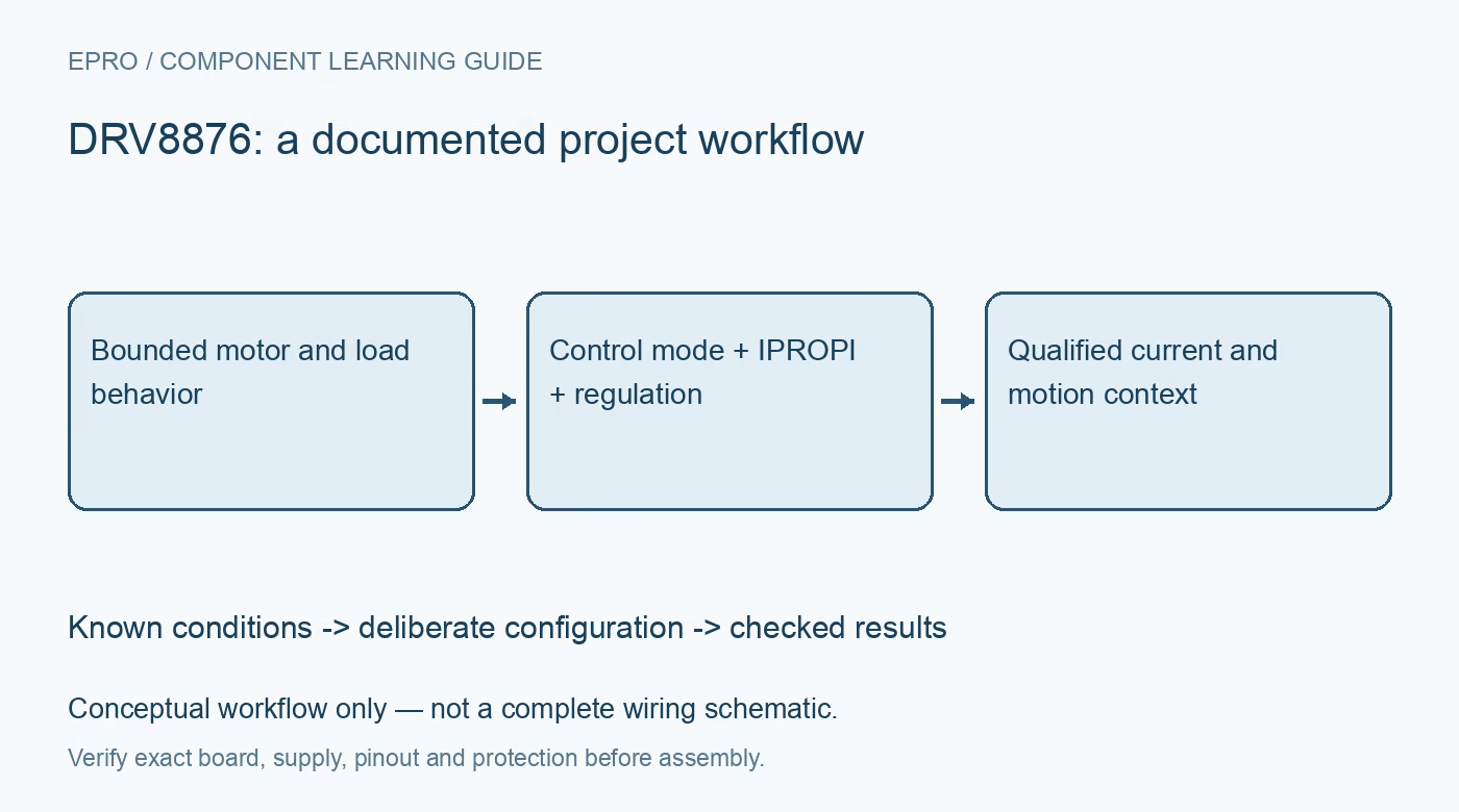
Plan DRV8876 motion with explicit control modes, IPROPI scaling, current-regulation settings, sensing-state limits, thermal budgets and qualified stall interpretation. This is a documentation-based planning guide, not a report of independent hands-on testing.
1. Define the DRV8876 motion requirement
DRV8876 integrates an H-bridge, current-sense functions and regulation features for motor and related loads. Identify the exact device and carrier before applying another family member’s current or thermal figures. Define the motor, mechanical travel and stopping behavior. An integrated current signal does not provide position feedback or prove that the mechanism moved correctly. Keep initial evaluation protected, low voltage and mechanically guarded, with a limited source and a deliberate way to remove power. Manufacturer documentation.
2. Select the actual input-control mode
PMODE changes the supported control arrangement, including phase/enable, PWM-related and independent half-bridge options. Use the documented truth table for the selected setting rather than inferring behavior from two GPIO names. Preserve the physical mode network with the firmware revision. Braking, coasting and sleep have different current and motion consequences. A software function called stop or disable is not enough evidence of the resulting terminal state, particularly during host reset or a disconnected control connection. Manufacturer documentation.
3. Scale IPROPI using the complete circuit
IPROPI provides a proportional current that an external resistor can convert into a voltage for the host ADC. Use the documented ratio, resistor tolerance and allowed operating conditions in the transfer model. Check ADC reference and input range as well as the driver output limit. Do not treat the pin as a ready-made digital current register. Preserve raw ADC values and configuration while evaluating scale so clipping or an unsuitable resistor cannot silently become an apparently reasonable motor-current estimate. Manufacturer documentation.
4. Preserve the current-sensing operating state
The documented sensing path observes current through the relevant low-side devices, including supported drive and brake conditions. Coast behavior does not provide the same direct sensing condition. Record control state and sample timing with current observations rather than assuming every PWM interval yields equivalent information. A low reported value during an unsuitable state is not proof of zero winding current. Account for switching and acquisition timing before using the signal in a fast control or diagnostic decision. Manufacturer documentation.
Newest in the store


5. Configure regulation separately from fault protection
Use VREF, the IPROPI network and IMODE according to the documented regulation relationship and policy. Current chopping and overcurrent fault protection serve different purposes. A peak headline rating is not the continuous current capability of every board. Include motor startup demand, driver losses and thermal layout in the budget. Do not repeatedly trigger protection or hold a motor stalled as an ordinary adjustment procedure. Evaluate through safe bounded conditions and suitable independent measurement equipment. Manufacturer documentation.
6. Qualify load and stall interpretations
Current feedback can help infer load changes, but it does not inherently distinguish a legitimate heavy load from every stall or mechanical fault. Establish startup exclusions, expected operating regions and any required external motion evidence. Keep nFAULT interpretation, sleep timing and recovery behavior distinct from application-level stall logic. A threshold chosen from one unloaded run is not a validated diagnostic boundary. Preserve motor identity, supply and mechanical conditions so a replacement mechanism does not silently invalidate the policy. Manufacturer documentation.
7. Keep motion evidence with electrical records
Retain mode, PWM policy, IPROPI scale, regulation settings, sampling state, thermal arrangement and observed motion conditions with results. Evaluate stopping and recovery under guarded procedures. The linked DRV8838 guide describes another control interface without equivalent integrated sensing responsibilities. This DRV8876 workflow proposes documentation-based load checks and reports no independent stall-detection accuracy, validated braking distance or safety certification of a finished actuator from an H-bridge current-feedback feature alone. Manufacturer documentation.
Related reading: DRV8838 Motor Driver: 7 Checks Before Treating Disable as Coast.
Catalog note: The exact-part search did not return a matching Epro listing during preparation. Check the current catalog; this guide makes no price, availability or included-accessory claim.