


PCA9306 I2C Translator: 7 Checks Beyond Two Supply Labels

PCA9306 I2C Translator: 7 Checks Beyond Two Supply Labels
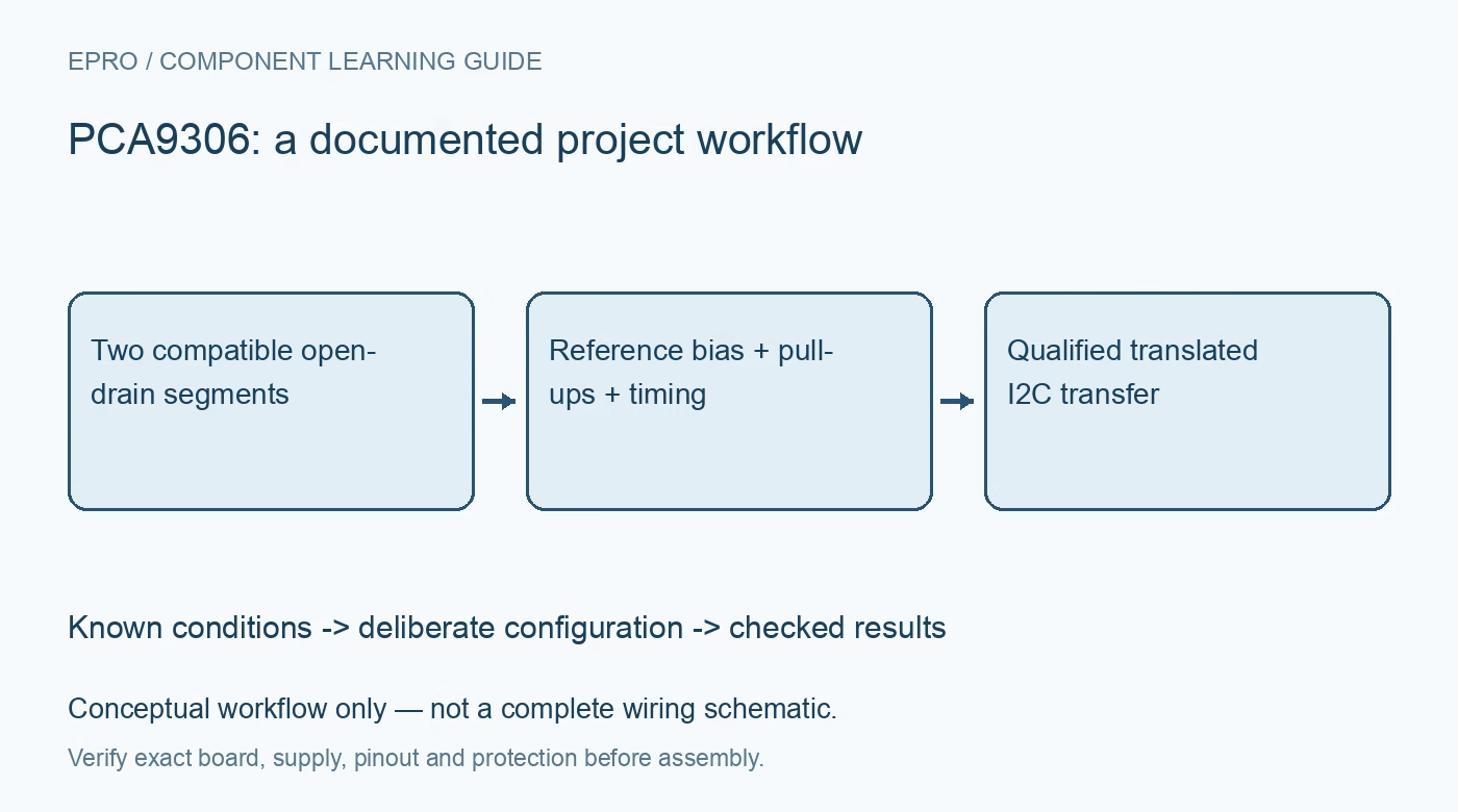
Plan PCA9306 translation with the correct reference and enable bias, segment pull-ups, sink-current limits, timing and powered-down behavior. This is a documentation-based planning guide, not a report of independent hands-on testing.
1. Define the PCA9306 electrical role
PCA9306 provides bidirectional voltage translation through a pass-switch arrangement for interfaces such as I2C. It is not a galvanic isolator and does not provide independent isolated power. Draw the two bus-voltage domains, common reference and all connected devices. Two supply labels on a module do not establish a complete compatible interface. Preserve the actual carrier schematic so installed pull-ups, reference bias and enable components are not mistaken for internal functions of the bare device. Manufacturer documentation.
2. Review VREF1, VREF2 and enable bias
Use the manufacturer reference and enable arrangement for the chosen voltages. The documented current-limiting bias path is not equivalent to treating every reference pin as an arbitrary directly driven supply input. Inspect the module before adding external wiring or changing a resistor. Preserve component values and the expected enabled state. A voltage measured at an idle bus does not prove that the translator is correctly biased during a low-level transfer or an independently unpowered condition. Manufacturer documentation.
3. Count pull-ups on both segments
Identify every pull-up already installed on controllers, sensors and breakout boards. Choose the combined resistance from bus capacitance, rise-time requirements and the available sink capability. Do not add a familiar resistor value blindly to each new board. Enabled segments are electrically connected through the translator for low-level signaling, so the endpoint current burden deserves attention. A strong pull-up can improve one timing issue while creating a low-level voltage or current-limit problem elsewhere in the interface. Manufacturer documentation.
4. Check low-level and endpoint compatibility
Verify that each endpoint recognizes the resulting low and high levels and can sink the required current. A bidirectional interface does not eliminate these thresholds. Keep introductory evaluation to appropriate protected low-voltage circuitry and use compatible measurement equipment. The translator is intended for the documented interface behavior; it is not a universal substitute for an actively driven logic translator. Confirm the actual open-drain signaling arrangement instead of assuming any two GPIO waveforms can be connected interchangeably. Manufacturer documentation.
Newest in the store


5. Evaluate complete-bus rise time
Propagation through a pass switch is only one part of the communication timing budget. Cable and board capacitance, pull-ups, device loading and operating speed determine whether signals reach valid levels in time. An address scan at a convenient speed does not establish reliable transfers under the intended installation conditions. Review timing with suitable instruments and representative wiring. Do not claim that the translator automatically buffers capacitance or makes a long bus equivalent to a short local connection. Manufacturer documentation.
6. Define enable and power-sequence behavior
Use the documented enable function to connect or disconnect segments deliberately. Review leakage, back-power and bias behavior when either domain is absent rather than relying on normal-operation readings alone. A disconnected segment is not necessarily reset, and changing enable does not remove duplicate addresses or repair every stuck peripheral. Keep timeout and recovery policies in the host. Preserve the intended control state through startup so temporary firmware defaults cannot silently expose a device to an unsuitable bus condition. Manufacturer documentation.
7. Separate translation from isolation claims
Retain reference voltages, bias network, pull-ups, endpoints, speed and wiring with communication results. Test real transactions rather than only idle voltage and address acknowledgment. The related ISO1540 guide describes an isolation barrier with separate responsibilities, not an equivalent PCA9306 connection. This workflow proposes documentation-based translation checks and reports no independent bus qualification, universal push-pull compatibility or hazardous-voltage protection. A successful I2C read verifies that transaction under its conditions, not every operating state of a mixed-voltage system. Manufacturer documentation.
Related reading: ISO1540 I2C Isolator: 7 Checks for a Complete Bus Barrier.
Catalog note: The exact-part search did not return a matching Epro listing during preparation. Check the current catalog; this guide makes no price, availability or included-accessory claim.