


TPS3431 Watchdog: 7 Checks for a Meaningful Falling Edge

TPS3431 Watchdog: 7 Checks for a Meaningful Falling Edge
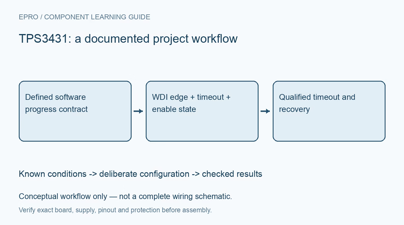
Plan TPS3431 supervision with a real firmware-health contract, valid WDI falling edges, timeout tolerances, enable states and a deliberate recovery path. This is a documentation-based planning guide, not a report of independent hands-on testing.
1. Define what TPS3431 supervision should prove
TPS3431 is a standard programmable watchdog timer. Begin with a concrete firmware-health contract: which work must finish before the host services it? An unrelated periodic interrupt can keep producing watchdog activity while the application is stuck. Tie service to meaningful progress rather than an unconditional background toggle. Record what the watchdog can and cannot detect. An external timer improves one failure-detection path but does not establish that every incorrect sensor result or software state will be recognized. Manufacturer documentation.
2. Use the documented WDI falling edge
The documented watchdog input requires a falling edge before its timeout expires. Holding WDI at an apparently active level is not equivalent to producing the required transition. Check pulse conditions and logic compatibility, including the GPIO behavior during host reset. Keep the service sequence explicit in firmware. A scope-visible edge can establish electrical activity under observed conditions; it does not establish that the software task responsible for the application result actually completed successfully before that edge. Manufacturer documentation.
3. Choose timeout from worst-case timing
Use the supported capacitor-programmed or preset timeout arrangement and account for the device limits and external component tolerance. The nominal timeout is not an exact deadline. Compare the shortest credible watchdog interval with the longest legitimate application cycle, including communication recovery and startup. Also compare the longest interval with the required fault response. A timeout copied from a demonstration can either create unnecessary resets or leave a stalled system unrecognized longer than the application can tolerate. Manufacturer documentation.
4. Verify CWD and SET configuration
Follow the documented CWD and SET1 configuration options for the intended timeout and disable behavior. Do not treat a floating pin as a universal safe default or assume that a capacitor always selects the same behavior as another watchdog family. Preserve the actual network in the board record. Development jumpers and assembly changes can alter the supervision policy without any firmware change. Review the final installed configuration rather than only the settings used during an early bench demonstration. Manufacturer documentation.
Newest in the store


5. Keep EN and ENOUT responsibilities clear
Review how the enable input, enable output and reset-delay timing interact. An intentionally disabled watchdog cannot detect missing service, so disable periods need a documented reason and bounded application policy. Define startup, low-power operation and recovery behavior rather than scattering enable changes across unrelated firmware routines. ENOUT is not simply another arbitrary copy of the watchdog input. Preserve its connection and meaning so the host cannot confuse an enable-related transition with an independent proof of completed work. Manufacturer documentation.
6. Design WDO and recovery as a complete path
Use the documented active-low open-drain watchdog output with a suitable pull-up and compatible reset or control input. Check behavior through power-up, timeout and host reset. The downstream recovery path matters as much as detecting a missing edge: a reset loop that never corrects the cause is not successful recovery. Evaluate controlled software stalls under protected conditions, not hazardous uncontrolled load faults. Preserve reset cause and fault history where the application needs post-event diagnosis. Manufacturer documentation.
7. Verify enabled operation after development
Retain timeout configuration, WDI contract, enable policy, output wiring and observed recovery timing with the firmware revision. Ensure temporary watchdog-disable settings do not remain in the deployed configuration accidentally. The related TPL5010 guide concerns a different wake-and-acknowledgment arrangement, not interchangeable timing or pins. This TPS3431 workflow proposes documented supervision checks. It claims no independent fault-coverage measurement, guaranteed recovery from every software error or safety certification merely because an external watchdog can assert an output. Manufacturer documentation.
Related reading: TPL5010 Watchdog Timer: 7 Checks for a Real Work-Cycle Ack.
Catalog note: The exact-part search did not return a matching Epro listing during preparation. Check the current catalog; this guide makes no price, availability or included-accessory claim.