


TPL5010 Watchdog Timer: 7 Checks for a Real Work-Cycle Ack

TPL5010 Watchdog Timer: 7 Checks for a Real Work-Cycle Ack
Plan TPL5010 wake and watchdog behavior with a resistor-selected interval, deliberate DONE acknowledgment, reset timing and complete-cycle energy checks. This is a documentation-based planning guide, not a report of independent hands-on testing.
1. Distinguish the TPL5010 from a power gate
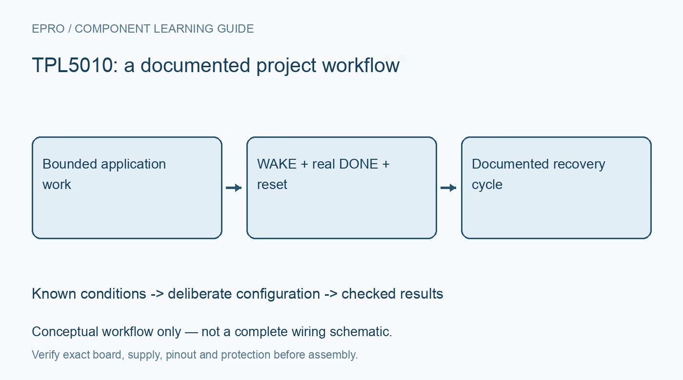
TPL5010 is a low-power system wake timer with a watchdog function. It supports duty-cycled host operation but should not be described as automatically removing the processor supply. Draw the always-powered timer, host and relevant peripherals separately. Define what wakes the host, what counts as completed work and what a reset should recover. This separates a firmware progress contract from the electrical power-gating function of other timer architectures. Manufacturer documentation.
2. Select the interval from documented timing
Use the manufacturer resistor-selection guidance and timing diagrams for the intended interval. Include tolerance and startup behavior in the application record rather than treating a nominal resistance as an exact universal period. Review how the delay configuration is established and how manual reset interacts with operation. The selected interval must support the real work cycle and recovery policy. Choosing a long delay merely to avoid resets can conceal a host task that is not reliably bounded. Manufacturer documentation.
3. Verify the host interface and reset path
Check supplies, logic levels, WAKE, DONE and reset connections against the exact board and host requirements. Review the documented output behavior and any required pull-ups. Ensure the host recognizes the wake event and that its reset input responds appropriately to the timer’s signal. A voltage-compatible GPIO connection alone does not establish the full sequence. Define pin states through processor boot, reset and low-power entry instead of analyzing only a running main loop. Manufacturer documentation.
4. Acknowledge completed work rather than activity
Define DONE around successful completion of the intended bounded task. Include sensor acquisition, required communication and persistent writes where they are part of the contract. An acknowledgment generated blindly by a periodic interrupt can keep the watchdog satisfied while the application is stuck elsewhere. Preserve the meaning of the acknowledgment in the firmware design. The aim is not merely to avoid resets, but to make absence of progress visible through the documented watchdog behavior. Manufacturer documentation.
Newest in the store


5. Respect timing windows and missed acknowledgments
Follow the manufacturer timing requirements for DONE and the watchdog sequence rather than issuing arbitrary pulses whenever convenient. Establish behavior for failed sensors, unavailable networks and operations that exceed the ordinary duration. Use bounded retries and record why a work cycle did not complete. A host should not falsely report success just to stay powered and running. Review what the timer does when acknowledgment is absent and ensure the application can tolerate that recovery action. Manufacturer documentation.
6. Design reset recovery as a complete operation
Consider the state of peripherals, external outputs and stored data when the host resets. Processor reset does not necessarily reset every sensor or remove power from an attached actuator. Reinitialize the required configuration and restore safe outputs deliberately. Avoid a repeated reset loop that endlessly retries the same unresolved condition without preserving useful diagnosis. The watchdog is one recovery mechanism, not proof that every electrical, mechanical or software fault has been corrected. Manufacturer documentation.
7. Evaluate energy and reliability separately
Retain interval configuration, interface wiring, work definition, acknowledgment timing, reset handling and observation conditions with evaluation results. Assess complete-cycle energy instead of inferring battery life from timer current alone. The related TPL5110 guide concerns external power gating and is not an interchangeable wiring plan. This TPL5010 workflow proposes traceable wake and recovery checks and claims no independent endurance tests, guaranteed software reliability or safety certification merely because a watchdog can reset the processor. Manufacturer documentation.
Related reading: TPL5110 Timer: 7 Steps to Reliable Power-Gated Projects.
Catalog note: The exact-part search did not return a matching Epro listing during preparation. Check the current catalog; this guide makes no price, availability or included-accessory claim.